background image

39

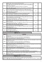
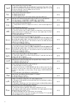
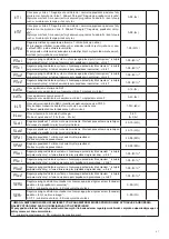
TM1

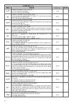
Tiempo trabajo motor 1. Ajusta el tiempo de funcionamiento con velocidad nor-
mal durante las fases de apertura y cierre del motor 1. Véase apartado “Regula-
ciones velocidad hoja”.
Programando el valor a 0 la maniobra es efectuada con aproximadamente 2s de 
arranque y prosigue ralentizada durante toda la carrera. 

0-99-(5s)

TM2

Tiempo trabajo motor 2. Ajusta el tiempo de funcionamiento con velocidad nor-
mal durante las fases de apertura y cierre del motor 2. Véase apartado “Regula-
ciones velocidad hoja”.
Programando el valor a 0 la maniobra es efectuada con aproximadamente 2s de 
arranque y prosigue ralentizada durante toda la carrera. 

0-99-(5s)

Tped

Regula el porcentaje de apertura del motor 1 (función peatonal).
Con motores con encoder, el valor se expresa (99% apertura con hoja).
Con motores que no tienen encoder o finales de carrera eléctricos, el valor se 
expresa en segundos. 

1-99 (50%)

PMo1

Ajusta el umbral de actuación del dispositivo anti-aplastamiento * (sensor ampe-
rimétrico) durante la fase de apertura a velocidad normal - motor 1

1-99-(50%)**

PMC1

Ajusta el umbral de actuación del dispositivo anti-aplastamiento * (sensor ampe-
rimétrico) durante la fase de cierre a velocidad normal - motor 1

1-99-(50%)**

PMo2

Ajusta el umbral de actuación del dispositivo anti-aplastamiento * (sensor ampe-
rimétrico) durante la fase de apertura a velocidad normal - motor 2

1-99-(50%)**

PMc2

Ajusta el umbral de actuación del dispositivo anti-aplastamiento * (sensor ampe-
rimétrico) durante la fase de cierre a velocidad normal - motor 2

1-99-(50%)**

TDMo

Tiempo de retardo de apertura Mot.2
Regula el tiempo de retardo de apertura del motor 2 respecto al motor 1

0-15-(2s)

TDMC

Tiempo de retardo del cierre Mot.1
Regula el tiempo de retardo del cierre del motor 1 respecto al motor 2

0-40-(3s)

TLS

Tiempo activación contacto SERL (Luz de posición) borneros 29/30.
En cada operación, el contacto se cierra durante el tiempo configurado. 
Consulte el esquema de conexión de la figura 4.

1-240-(60s)

TLOc

Tiempo de activación de la electrocerradura. 
Valor expresado en 1/10se (0=0s - 50=5s)

0-50 

(5=0,5s)

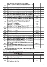
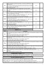
SLD1

Regula la velocidad del motor 1 durante las fases de ralentización. Valor expresado 
en porcentaje respecto a la velocidad de funcionamiento normal.

30-70 (40%)

SLD2

Regula la velocidad del motor 2 durante las fases de ralentización. Valor expresado 
en porcentaje respecto a la velocidad de funcionamiento normal.

30-70 (40%)

SpD1

Regula la velocidad del motor 1 durante la fase de velocidad normal. 
Valor expresado en porcentaje.

30-99 (99%)

SpD2

Regula la velocidad del motor 2 durante la fase de velocidad normal. 
Valor expresado en porcentaje.

30-99 (99%)

Pso1

Ajusta el umbral de actuación del dispositivo anti-aplastamiento * (sensor ampe-
rimétrico) durante la fase de apertura a velocidad ralentizada - motor 1

1-99-(20%)**

Psc1

Ajusta el umbral de actuación del dispositivo anti-aplastamiento * (sensor ampe-
rimétrico) durante la fase de cierre a velocidad ralentizada - motor 1

1-99-(20%)**

Pso2

Ajusta el umbral de actuación del dispositivo anti-aplastamiento * (sensor ampe-
rimétrico) durante la fase de apertura a velocidad ralentizada - motor 2

1-99-(20%)**

Psc2

Ajusta el umbral de actuación del dispositivo anti-aplastamiento * (sensor ampe-
rimétrico) durante la fase de cierre a velocidad ralentizada - motor 2

1-99-(20%)**

SeaU

Ajusta el umbral de actuación del dispositivo antiaplastamiento (encoder) durante 
la fase con velocidad normal*. 
0:Off -1: mínima sensibilidad - 99: máxima sensibilidad

0-99-(0%)

SEAR

Ajusta el umbral de actuación del dispositivo antiaplastamiento (Encoder) durante 
la fase de ralentización*.
0:Off -1: mínima sensibilidad - 99: máxima sensibilidad

0-99-(0%)

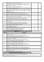
* ATENCIÓN: UNA CONFIGURACIÓN ERRÓNEA DE ESTOS PARáMETROS PUEDE RESULTAR PELIGROSA. 
¡AJUSTARSE A LAS NORMAS VIGENTES!
Con motores que no tienen final de carrera o encoder, regula la sensibilidad del sensor que genera la parada durante la 
fase de ralentización.

** 1: mínima fuerza/par - 99: máxima fuerza/par

Содержание BRAINY 24

Страница 1: ...L8542589 05 2011 rev 0 BRAINY 24 UNIONE NAZIONALE COSTRUTTORI AUTOMATISMI PER CANCELLI PORTE SERRANDE ED AFFINI...

Страница 2: ...x SWO1 ENC1 SWC1 SWO2 ENC2 SWC2 PHOT PHOTC STOP OPEN CLOSE PED P P COM ENC ENC COM ENC F1 T 2A DAS J1 DAS Open DAS N C J1 DAS Close DAS 8K2 28 27 1 2 3 4 5 6 7 8 9 10 11 12 13 14 15 16 17 18 19 20 21...

Страница 3: ...NCODER ENCODER WIRING 2 3 4 24Vac 24Vac COM NC NO RX1 TX1 24Vac 24Vac COM NC NO RX2 TX2 11 24Vac COM PHOT COM PHOT C 24Vac 12 11 12 13 18 13 19 9 10 9 10 test1 on test2 ON SCA AUX1 0 AUX1 2 SERVICE ZO...

Страница 4: ...o per l installazione e la manutenzione di aperture automatiche Nessuna informazione qui presente di interesse o di utilit per l utente finale Conservare questo manuale per futuri utilizzi L installat...

Страница 5: ...cabatteria l uscita in assenza di alimentazione di rete presenta una tensione 24Vdc polarizzata Verificare il corretto collegamento dei dispositivi 11 24Vdc 12 0Vdc 13 COM ENC Comune per finecorsa e t...

Страница 6: ...e se utilizzati i relativi ingressi di finecorsa 14 15 per il motore M1 e 16 17 per il motore M2 Programmazione La programmazione delle varie funzionalit della centrale viene effettuata utilizzando il...

Страница 7: ...a il contatto si chiude per il tempo impostato Vedere schema di collegamento Figura 4 1 240 60s TLOc Tempo attivazione elettroserratura Valore espresso in 1 10s 0 0s 50 5s 0 50 5 0 5s SLD1 Regola la v...

Страница 8: ...lo sgancio dell elettroserratura Off Funzione disabilitata OFF Blco Abilita o disabilita la funzione di blocco in apertura On Funzione blocco abilitato Da utilizzare solo con motori dotati di fine co...

Страница 9: ...otori On Verifica abilitata Se la verifica ha esito negativo non viene comandata nes suna manovra Off Verifica disabilitata OFF rem Abilita o disabilita l apprendimento remoto dei radiotrasmettitori c...

Страница 10: ...ei parametri Inizialmente entrambe le ante vengono portate in posizione di apertura quindi dopo alcune manovre di apertura e chiusura a di verse velocit di una o di entrambe le ante la centrale visual...

Страница 11: ...ti dai segmenti orizzontali La centrale visualizza il messaggio AMP1 o AMP2 in caso di intervento del sensore am perometrico antischiacciamento MESSAGGI DI ERRORE Di seguito sono elencati alcuni messa...

Страница 12: ...WARNINGS This manual has been especially written to be use by qualified fitters None of the information provide in this manual can be considered as being of interest for the end users Preserve this ma...

Страница 13: ...ST1 and TEST2 logics must be OFF For use as photocell test it is sufficient to activate one or both TEST logics and connect the photocells as indicated in Fig 3 11 12 24 Vac dc Output accessory power...

Страница 14: ...M1 motor and 16 17 for M2 motor PROGRAMMING The programming of the various functions of the control unit is carried out using the LCD display on the control unit and setting the desired values in the...

Страница 15: ...osing with respect to motor 2 0 40 3s TLS SERL contact activation time Service light 29 30 terminals At each manoeuvre the contact closes for the set time See Figure 4 connection scheme 1 240 60s TLOc...

Страница 16: ...sables the block function in opening On Block function enabled To use only with motors equipped with Limit switch After the intervention of the opening Limit switch the control unit delays arrest by a...

Страница 17: ...d Off Remote learning not enabled OFF RADIO RAD MENU FUNZIONE PP By selecting this function the receiver goes in waiting Push for a transmitter code to assign to the step step func tion Press the key...

Страница 18: ...fter some opening and closing manoeuvres at different speeds of one or both the shutters the control unit displays the message OK In case the operation has no positive result the message ERR is displa...

Страница 19: ...e N C inputs are represented by the vertical segments N O inputs are represented by the horizontal segments The control unit sees the message AMP1 or AMP2 in case of anti crushing ammeter sensor inter...

Страница 20: ...omatischen ffnungsvorrichtungen bestimmt Es enth lt keine Informationen die f r den Endbenutzer interessant oder n tzlich sein k nnten Bewahren Sie dieses Handbuch f r Nachschlagzwecke auf Der Install...

Страница 21: ...ter TEST1 und TEST2 auf OFF stehen F r den Gebrauch als Fotozellentest gen gt es eine oder beide Logikschalter TEST zu aktivieren und die Fotozellen wie in Abb 3 angezeigt anzuschlie en 11 12 24 Vac d...

Страница 22: ...5 f r die Motore M1 und 16 17 f r Motor M2 Programmierung Die Programmierung der verschiedenen Funktionen der Steuerzentrale erfolgt ber das LCD Display an der Zentrale selbst indem die gew nschten We...

Страница 23: ...ngszeit Kontakt SERL Innenleuchte Klemmen 29 30 Bei jeder Bewegung schlie t sich der Kontakt f r die Dauer der eingestellten Zeit Siehe Anschlussplan Abbildung 4 1 240 60s TLOc Aktivierungszeit Elektr...

Страница 24: ...en mit Endschalter zu benutzen Nach dem Eingreifen der ffnungsendschalter verz gert die Zentrale den Halt um etwa 0 5s damit ein besserer Anschlag des Fl gels in die Arrettierungen erm glicht wird Off...

Страница 25: ...er Funkger te wie im Abschnitt Fern bernahme Funkger te On Fern bernahme freigeschaltet Off Fern bernahme nicht freigeschaltet OFF RADIO RAD MENU FUNZIONE PP Bei Wahl dieser Funktion setzt sich der Em...

Страница 26: ...geln zeigt die Zentrale die Meldung OK an Wenn der Vorgang ohne positives Ergebnis bleibt wir die Meldung ERR Wiederholen Sie den Vorgang erneut nachdem Sie die Verkabelungen berpr ft aben und sicher...

Страница 27: ...normalerweise geschlossenen Eing ngen entsprechen die vertikalen Segmente Den normalerweise offenen Eing nge entsprechen die horizontalen Segmente Die Zentrale zeigt die Meldung AMP1 oder AMP2 an wen...

Страница 28: ...es Aucune information donn e dans ce manuel ne sera d in t r t ou d utilit a l utilisateur final Conservez ce manuel pour de futures utilisations L installateur doit donner tout renseignement relatif...

Страница 29: ...iques TEST1 et TEST2 doivent tre OFF Pour utilisation comme test photocellules il suffit d activer une ou les deux logiques TEST et de connecter les photocellules de la fa on indiqu e sur la Fig 3 11...

Страница 30: ...its ci apr s Le menu param tres permet d associer une valeur num rique une fonction comme pour un trimmer de r glage Le menu des logiques permet d activer ou de d sactiver une fonction comme pour le r...

Страница 31: ...t la vitesse de fonctionnement normal 30 70 40 SpD1 R gle la vitesse du moteur 1 durant la phase de vitesse normale Valeur exprim e en pourcentage 30 99 99 SpD2 R gle la vitesse du moteur 2 durant la...

Страница 32: ...urs do t s de fins de course Apr s l intervention des fins de course d ouverture l ar moire retarde l arr t d environ 0 5s de mani re consentir une meilleure but e du battant sur les dispositifs d arr...

Страница 33: ...le code n est pas valide le message ERR s affiche 2Ch En s lectionnant cette fonction la r ceptrice se met en attente Push d un code metteur attribuer au second canal radio lectrique Presser la touche...

Страница 34: ...s r p ter la proc dure d autoset Durant les man uvres l cran affiche certains sigles OPM1 OPM2 durant l ouverture du moteur 1 ou 2 et CLM1 CLM2 durant la fermeture du moteur 1 ou 2 PROTECTION D ACC S...

Страница 35: ...l cran en cas d anomalies de fonctionnement Amp1 Erreur obstacle moteur 1 anti crasement V rifier la pr sence d obstacles sur la course du battant moteur 1 Amp2 Erreur obstacle moteur 2 anti crasement...

Страница 36: ...instalaci n y el mantenimiento de aper turas autom ticas Ninguna informaci n de las aqu presentadas es de inter s o de utilidad para el usuario final Guardar este manual para futuras consultas El inst...

Страница 37: ...rta o test fotoc lulas Para utilizar como Indicador cancela abierta las l gicas TEST1 y TEST2 deben estar en modo OFF Para utilizar como test fotoc lulas bastar con activar una o ambas l gicas TEST y...

Страница 38: ...M2 y si se utilizan las entradas de final de carrera correspondientes 14 15 para el motor M1 y 16 17 para el motor M2 Programaci n La programaci n de las diferentes funciones de la centralita se efect...

Страница 39: ...el contacto se cierra durante el tiempo configurado Consulte el esquema de conexi n de la figura 4 1 240 60s TLOc Tiempo de activaci n de la electrocerradura Valor expresado en 1 10se 0 0s 50 5s 0 50...

Страница 40: ...ci n deshabilitada OFF Blco Habilita o deshabilita la funci n de bloqueo en apertura On Funci n bloqueo habilitado Se utiliza solamente con motores que cuentan con final de carrera Despu s de la inter...

Страница 41: ...ada operaci n deshabilitada OFF TSTm Habilita o deshabilita el control de los motores On Control habilitado Si el control no se realiza con xito no se controla ninguna operaci n Off Control deshabilit...

Страница 42: ...para memorizar el recorrido de las hojas y para configurar los par metros En principio ambas hojas se colocan en posici n de apertura luego despu s de algunas maniobras de apertura y cierre a distint...

Страница 43: ...ntales La central muestra el mensaje AMP1 o AMP2 en caso de intervenci n del sensor ampe rom trico antiaplastamiento MENSAJES DE ERROR A continuaci n se muestran algunos mensajes que se visualizan en...

Страница 44: ...nego personelu w celu instalacji I konserwacji bram automatycznych adna z zawartych tu informacji nie jest u yteczna ani celowa dla ko cowego u ytkownika Przechowywa niniejszy podr cznik do przysz ego...

Страница 45: ...ej bramy lub test fotokom rek W przypadku zastosowania jako Kontrolka otwartej bramy dla logiki TEST1 i TEST2 nale y ustawi warto OFF W przypadku zastosowania jako test fotokom rek wystarczy uaktywni...

Страница 46: ...lnika 1 2 dla silnika M1 i 3 4 dla silnika M2 oraz odpowiednie wej cia wy cznik w kra cowych je li s u ywane 14 15 dla silnika M1 i 16 17 dla silnika M2 Programowanie Programowanie r nych funkcji cent...

Страница 47: ...zaciski 29 30 Przy ka dym manewrze kontakt zamyka si na ustalony czas Schemat pod cze zosta pokazany na Rysunku 4 1 240 60s TLOc Czas w czania zamka elektrycznego Warto wyra ona w 1 10s 0 0s 50 5s 0...

Страница 48: ...Stosowana tylko z silnikami wyposa onymi w wy czniki kra cowe Po zadzia aniu wy cznik w kra cowych otwierania centralka op nia zatrzymanie o oko o 0 5 s w ten spos b skrzyd o lepiej uderza w blokady...

Страница 49: ...w On Zdalne zapami tywanie nadajnik w za czone Off Zdalne zapami tywanie nadajnik w nieza czone OFF RADIO RAD MENU FUNZIONE PP Po wybraniu tej funkcji odbiornik przechodzi w tryb oczekiwania Push na k...

Страница 50: ...ie po kilku manewrach otwierania i zamykania z r nymi pr dko ciami jednego lub obu skrzyde centralka wy wietla komunikat OK Je eli operacja nie zako czy si pozytywnym wynikiem zostaje wy wietlony komu...

Страница 51: ...ziome Centralka wy wietla komunikaty AMP1 lub AMP2 w przypadku zadzia ania czujnika am perometrycznego zapobiegaj cego przygnieceniu KOMUNIKATY O B DZIE Poni ej zosta y wyszczeg lnione komunikaty wy w...

Страница 52: ...FO BMT 4DIBSOJFS EJF OFOEFO 4DISBVCFO MPDLFSO BCFS OJDIU BVTCBVFO EBNJU EFS FDLFM HF GGOFU XFSEFO LBOO 1SFTTFS MFT EFVY BJMFUUFT MBU SBMFT QPVS E DSPDIFS MFT EFVY DBDIF WJT OMFWFS MFT EFVY WJT TVS MF...

Отзывы: