background image


5) 

Fill the container with the specified fuel - see chapter 3. Then 

close the container carefully

 to 

prevent the intake of false air in the burner through the feed worm. 

6) 

Connect the boiler to the electrical power network (230V/50Hz) with the cable and the plug. 

7) 

If the boiler is equipped with automatic ignition

, don’t take further steps as the Boiler Control 

Unit  analyses  the  state  of  the  boiler  and  takes  further  steps  such  as  heating  etc.  (see  the 
separate  Instruction Control Unit  user`s manual). During heating up and subsequent operation 
of the boiler, the fire door must be closed. 

8) 

If  the  boiler  is  not  equipped  with  automatic  ignition, 

it  is  necessary  to  heat  the  boiler 

manually  (see  the  separate  Boiler  Control  Unit  users’  manual).  Use  the  manual  mode  on  the 
Control  Unit  to  transport  the  fuel  to  the  combusting  area.  Leave  the  worm  feeder  switched  on 
until the fuel appears in the burner (approx. 1 cm under the grate rim). Then switch off the worm 
feeder,  place  some  kindling  (paper,  dry  wood  chips,  solid  alcohol  or  some  other  fire  lighter 
recommended for these purposes) on the top of the fuel, set it alight and wait until it begins to 
burn (1-2 min.) Then add a small amount of specified fuel and switch on the ventilator. If the fire 
extinguishes, repeat the whole process. Close the door and let the fire begin to burn (3-5 min). 


7.2.  Operation of the boiler  

 
After  the  fuel  begins  to burn, the  boiler  switches to automatic operation (see the separate Control Unit 
user manual) during which the ventilator and the cycling of the worm feeder are in operation. The main 
information about the heating is shown on the display of the Control Unit. 
 
In case of blackout of the supply voltage (230 V, 50 Hz), the Instruction Control Unit keeps in memory 
the last data and after the voltage recovery, it returns to the previous state. 
 
If  the  temperature  of  the  heating  water  rises  over  95°C,  the  emergency  thermo  regulator  begins 
operation and, independently of the Control Unit, the boiler will be cut off. The Control Unit then displays 
overheating of the boiler. 
The emergency thermo regulator can only be switched on again after the temperature sink

s about 20°C 

below the set temperature. In this case, unscrew the black cap on the emergency thermo regulator and 
press the red switch. Then return the black cap to its position. 
To prevent an undesirable switching of the emergency thermo regulator, it is  recommended to operate 
the boiler at a maximum output water temperature lower than 80°C. 
In case  of  frequent switching off, the boiler must be shut down and the cause of repeated overheating 
must be established. 


7.3.  Boiler shutdown 

 
Before the boiler is shut down, burning fuel must be ejected from the burner to the ashtray manually by 
means  of  the  worm  conveyor.  This  operation  is  not  necessary  in  case  of  short  time  repairs  and  if  the 
operator is present. 

In  case of a shut down longer than 12 hours 

(e.g. cut out),

 the container must be emptied 

and if 

there is a possibility that the water in the emergency extinguishing system can freeze, it is necessary to 
empty the pressure tank as well. 


IMPORTANT WARNINGS: 


This  appliance  cannot  be  operated  by  persons  (including  children)  who  are  not 

physically,  sensorially  or  mentally  fit  to  do  so  and  have  insufficient  knowledge  and 
experience needed in order to operate the boiler safely. 


Children must not be left unattended in the proximity of a running boiler. 


Due  to  danger  of  explosion  or  fire  hazard  caused  by  entry  of  flammable  vapours  in 

the  fire  room,  during  any  works  that  involve  use  of  flammable  substances  (gluing  of  PVC, 
painting with flammable paint etc.) the boiler must be shut down. 

Содержание R100

Страница 1: ...1 SERVICE AND INSTALLATION MANUAL FOR CENTRAL HEATING BOILER BENEKOV R100 ...

Страница 2: ...with the instruction received from the producer and from the service company that installed the boiler This boiler has been approved for operation within the EU by the Engineering Test Institute s p notified person ES 1015 authorized person 202 Brno certificate no B 30 00311 14 from 30 4 2014 In accordance with the Government Order no 176 2008 Coll appendix 1 art 1 7 4 this is the ORIGINAL SERVICE...

Страница 3: ...l wiring 6 2 Connecting the boiler to the heating system 6 3 Installing the ceramic parts 6 4 Check before use 6 5 Boiler startup 13 13 15 16 17 18 7 Attendance by the user 7 1 Heating up in the boiler 7 2 Operation of the boiler 7 3 Boiler shutdown 7 4 Residual risks and their prevention 19 19 19 19 20 8 Boiler maintenance 21 9 Troubleshooting 22 10 Instructions for long term keeping of ecologica...

Страница 4: ...d burning operated by a lambda probe heat output modulation in whole output range the boiler including the boiler body consists of several smaller parts which makes its transportation on site and installation easier up to date design 2 Technical data Table 1 Dimensions and technical data Boiler type BENEKOV R100 Weight kg 1470 Water capacity dm 3 370 Chimney diameter mm 250 Heat transfer surface m...

Страница 5: ...nd full container h 13 Exhaust gas temperature at nominal power C 143 at minimum power C 89 Efficiency 89 Mass flow rate of exhaust gas at the output at nominal power kg s 1 0 048 at minimum power kg s 1 0 022 3 Approved fuel Table 3 states the approved guarantee fuel for the BENEKOV R100 boiler Table 3 Approved fuel Type of fuel Diameter mm Length mm Strewn weight kg m 3 Water content Ash content...

Страница 6: ...es complete burning of fuel Next to the boiler the fuel container is situated which is connected to the worm conveyor Its capacity can be extended by installing an additional module optional Depending on the position of the container in relation to the boiler the boiler is produced in two versions right handed version the container is situated on the right side of the boiler from the front view le...

Страница 7: ...10 cover of fuel feeder 11 primary air ventilator 12 cleaning door of heat exchanger 13 connecting piece of combustion chamber and exchanger 14 exhaust gas extractor 15 flue gas temperature sensor 16 extinguishing safety sytem 17 turnstile drive 18 control unit switchboard with safety thermostat 19 automatic ignition 20 fuel worm conveyor 21 worm fuel conveyor drive 22 exchanger cleaning system dr...

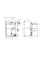
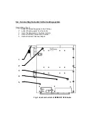
Страница 8: ...Fig 2 Basic dimensions of BENEKOV R100 boiler ...

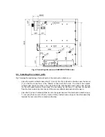
Страница 9: ...Fig 3 Basic dimensions of BENEKOV R100 boiler with additional module of fuel bin ...

Страница 10: ...a plastic reservoir If the boiler is equipped with a thermostatic valve with pressure tank optional and the temperature at the bottom of the fuel container rises over 95 C the thermostatic valve opens and the bottom of the fuel container is filled with water from the water supply system or from the installed water pressure tank Firing flap is placed among the second and third pass in the upper par...

Страница 11: ... buildings safety devices ČSN 07 7401 1992 Water and steam in thermal energetic devices operating with the running pressure to 8 Mpa B regulations concerning the chimney ČSN 73 4201 2010 Chimneys and smoke flues projects realization and connection of fuel appliances C regulations concerning the fire regulations ČSN 06 1008 1997 Fire safety of heating installations ČSN EN 13 501 1 1 A1 2010 Fire sa...

Страница 12: ...cerning appliances for combustion of gas oil or solid fuel equipped with electrical connections ČSN EN 60445 ed 3 2007 Basic safety principles for the human machine interface marking and identification Marking the appliance terminals and conductor ends ČSN EN 60445 ed 2 2011 Basic safety principles for the human machine interface marking and identification Marking of conductors with colours or let...

Страница 13: ...ith the valid ČSN EN standards see chapter 5 1 Location of the boiler with respect to fire regulations 1 Location on a fire resistant floor Place the boiler on a fireproof thermally insulating surface that overreaches the base of the boiler in all directions by at least 20 mm If the boiler is placed in the cellar it is recommended to place it on a bedding at least 50 mm high The boiler has to be h...

Страница 14: ...uel at least 1000 mm from the boiler or to store it in a separate room Permanent air circulation for burning and ventilation must be provided in the room where the boiler is installed Air consumption of BENEKOV R100 boiler at nominal power is approximately 300 m 3 h 1 Connection of the pipeline of the heating system or pipeline of the heating element must be carried out by a certified person WARNI...

Страница 15: ...ide the boiler Before startup these have to be installed on the switchboard even if they are not used When installing the connectors it is necessary to make sure that the right connectors are connected i e it is only allowed to connect plug contacts and plugs with identical symbols Prior to connecting the room thermostat or equithermal regulation it is necessary to remove the jumper from the conne...

Страница 16: ...4 1 outlet of combustion gases in the chimney 2 outlet of heating water from the boiler 3 inlet of heating water in the boiler return 4 inlet and outlet of combustion chamber 5 inlet and outlet of heat exchanger Fig 5 Inlets and outlets of BENEKOV R100 boiler 1 2 3 4 5 ...

Страница 17: ... side of the ceramic reflector with hole 2 must be on the right side for the right handed version and on the left side for the left handed version front view The secondary air inlet pos 5 can then be inserted from the boiler side in the inner cavity of the ceramic reflector and pushed all the way in place the 2 pieces of ceramic plates 6 onto the upper beams of the combustion chamber pos 7 securin...

Страница 18: ...of the heating system with water Necessary to ensure thorough filling the boiler and the entire heating system water and its proper venting When filling the boiler heating water should be kept in mind that the boiler body is composed of two interconnected vessels hill combustion chamber exchanger so you need to fill both of these vessels separate holes see fig 5 poz 4 a 5 The water used in the hea...

Страница 19: ...heating system does not leak c connection to the chimney must be approved by a chimney service company d connection to the electrical power network The sockets should be connected with the earthing contact at the top and the phase wire on the left side front view The same applies to double sockets Installation and stoking test must be recorded in the certificate of warranty 6 5 Boiler startup 1 If...

Страница 20: ...Control Unit keeps in memory the last data and after the voltage recovery it returns to the previous state If the temperature of the heating water rises over 95 C the emergency thermo regulator begins operation and independently of the Control Unit the boiler will be cut off The Control Unit then displays overheating of the boiler The emergency thermo regulator can only be switched on again after ...

Страница 21: ...y grows damp and low temperature corrosion occurs which shortens the service life of the boiler That s why the boiler must be operated at the temperatures higher than 60 C After the end of the heating season the boiler and the chimney must be cleaned carefully The fire room must be kept clean and dry It is strictly forbidden to tamper with the construction and electrical system of the boiler 7 4 R...

Страница 22: ...ity If the boiler runs continuously it is recommended to clean the heat transfer surface of the body of the boiler once a month The heat exchange surfaces become contaminated in course of the operation which may significantly impair the heat transfer and the efficiency of the boiler It is also important to clean occasionally once a month the inner part of the grate as any possible sediments influe...

Страница 23: ... If the pressure is not sufficient adjust it to 0 5 bar with an air pump or a compressor The worm feeder drive gear and the turniket drive gear are filled with synthetic oil from the production and further maintenance is not required 9 Troubleshooting If problems with operation of the boiler appear try one of the following solutions SYMPTOM REASON SOLUTION The display shows no data The boiler is n...

Страница 24: ...cy extinguishing system drops in the fuel container The paraffin plug is not tight Change the thermostatic valve Water drops appear on the walls of fuel container Wet fuel is used in the boiler Fill the container with dry fuel Low temperature in the fire room 12 C and less It is necessary to ensure higher temperature of the fire room insulation of fire room walls installation of a heating body in ...

Страница 25: ...he rubber sealing The fuel container is empty Fill the fuel container with fuel The boiler is coated with smoke particles in a short period of time Low amount of agitated air Raise the ventilator capacity see Instruction Control Unit manual The boiler is repeatedly overheated Set the boiler capacity to the nominal capacity see Instruction Control Unit manual The grate is full of dust and ash Clean...

Страница 26: ...an authorized service company that is certified by BENEKOVterm s r o Otherwise the guarantee of proper function of the boiler becomes invalid An important condition for the guarantee to be valid is connection of the boiler to the heating system in such way that the temperature of the return water is controlled automatically and does not fall under 55 60 C This condition can be fulfilled by using a...

Страница 27: ...ation common wear voluntary damage and damage that occurred as a result of irreversible and uncontrolled event fire flood burglary violent waste etc The certificate of warranty must be filled in by the seller to become valid The producer reserves the right to introduce changes as a result of innovation of the product that are not mentioned in this manual ...

Страница 28: ...NOTICE Please send the completed certificate of warranty for the producer of BENEKOV R100 boiler to the address below BENEKOVterm s r o Masarykova 402 793 12 Horní Benešov Czech Republic ...

Страница 29: ...omer supplement to the certificate of warranty Record of the validated guarantee and post guarantee repairs and about action taken Record date Action taken Service company signature stamp Signature of the customer ...

Страница 30: ...30 Declaration of conformity of boiler BENEKOV R 100 ...

Страница 31: ...31 Original ES declaration of conformity of boiler BENEKOV R 100 ...

Страница 32: ...BENEKOVterm s r o Masarykova 402 CZ 793 12 Horní Benešov Phone 420 554 748 008 Fax 420 554 748 008 E mail info benekov com www benekov com Edition 2014 07 ...

Отзывы: