


LifeGuard®
LG
2
-
Series
5
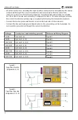
Figure W3 -
Three-Phase, Four-Wire
Configurations (L1, L2,
L3, N)
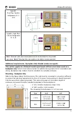
Figure W4 - Single-Phase
120/240 V Configurations
(L1, L2, N)
Note 1
:
Disconnect switch, branch circuit protection and/or overload relay
must
be provided
separately
.
Note 2
: Three-phase three-wire supplies can be solidly or resistance grounded.
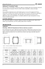
This section applies to LifeGuard models purchased without an enclosure and on a
backplate only
. Refer to instructions below for additional requirements for installation and
wiring. Backplate-only models must be installed in a suitable enclosure.
Mounting - Backplate Only
Refer to
the figure
below for dimensions. The unit must be mounted in a location sufficient
to protect live electrical equipment. Use four #10 screws for mounting. It should be placed
X inches away from other equipment. This vertical clearance X (minimum depth of
enclosure, measured from the installed backplate) of the backplate is:
7L4
5L3
3L2
1L1
8T4
6T3
4T2
2T1
Note 1
Note 1
B D
A
C
CT
Type
A x B
C x D
< 100 A
8.
2
5“ x 10.
2
5
(2
10
x 2
60
)
8.
88
“ x 10.
88
“
(2
25
x 2
76
)
100 A
12.
2
5“ x 14.
2
5“
(3
11
x 3
62
)
12.
88
“ x 14.
88
“
(3
27
x 3
78
)
• 6” (152 mm) for models less than 100 A
• 8” (203 mm) for 100 A models.
The mounting hole diameter is
1
/
4
“ (
6
.
4
mm).
Additional requirements - Backplate-Only Models (enclosure type
N
)
7L4
5L3
3L2
1L1
8T4
6T3
4T2
2T1
L1
L2
L3
N
Line
Load
GND
1
Note
L1
L3
N
L2
GND
CT
600
480
277
240
208
120
CPT
7L4
5L3
3L2
1L1
8T4
6T3
4T2
2T1
L1
L2
N
Line
Load
GND
Note 1
Note 1
L1
L2
N
GND
CT
600
480
277
240
208
120
CPT


