13
TGH 1360E
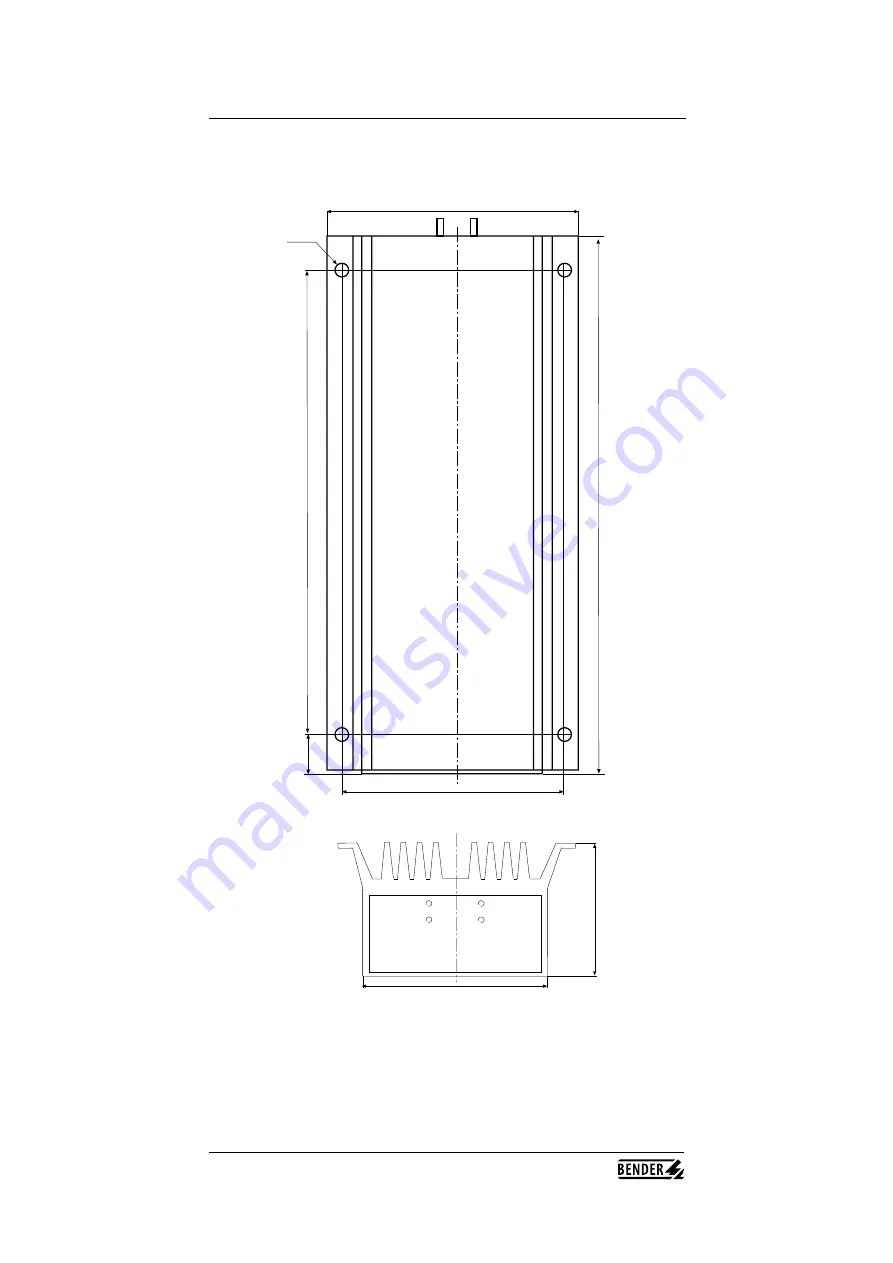
Product description
Dimensions coupling device AG5002
130
143
Ø 6,5
260
302
22
80
103
Страница 1: ...g device for IT DC systems 350 800 V IR5002 Operating Manual TGH 1360E Edition 04 2008 Quality System Certified I S O 9 0 0 1 MiniMax IR5002 ALARM L ALARM L ENTER k MONITOR BENDER A ISOMETER IR5002 Ve...
Страница 2: ...Tel 06401 807 0 Fax 06401 807 259 E Mail info bender de com IR5002 Operating manual TGH 1360E Edition 04 2005 Edited by Dipl Ing W BENDER GmbH CoKG This manual may not be copied in whole or part with...
Страница 3: ...diagram 14 Legend to wiring diagram 15 Terminal strips 16 5 Setting and operation 17 Function keys 17 Welcome screen 17 Main screen 17 Menus 18 The individual menus 19 Setting the response values 19...
Страница 4: ...y of power supply is concerned the IT system i e the unearthed system is the right choice In contrast to the earthed system the first insulation fault does not lead to a disconnection Combined with a...
Страница 5: ...fferent parameters The measured values can be transmitted to peripheral devices e g computers or PLC via serial interfaces The device parameter settings are stored in a non volatile EEPROM The values...
Страница 6: ...ve read and understood the safety chapter and the warning information in this operating manual The copyright to this operating manual shall remain with the BENDER Companies The operating manual is sol...
Страница 7: ...IR5002 Explanations of symbols and warnings The IR5002 is constructed according to the state of the art and the recognized safety engineering rules Nevertheless when it is being used hazards may occur...
Страница 8: ...ange of a product which has been sent to BENDER within the warranty period The qualifying conditions are that BENDER shall recognize the product as being faulty and that the fault cannot be attributed...
Страница 9: ...ome respect the measuring time is dependent on the system leakage capacitances CE and CE illustrated below The capacitances are always recharged when the coupling switches are closed resp opened inter...
Страница 10: ...ng principle This entails some specialities regarding the measured insulation values If the relation between the single insulation values RF and RF is high asymmetrical faults the accuracy of the high...
Страница 11: ...monitored as well as to the optional coupling device AG5002 The lower terminal box contains terminals for PE coupling supply voltage contacts of the alarm relay serial interfaces temperature sensor i...
Страница 12: ...12 TGH 1360E side view right Product description top view General dimensions according to DIN 7168 dimensions in mm 147 327 71 277 203 5 4 2 100 100 80 227 237 277 front view Dimension diagrams...
Страница 13: ...13 TGH 1360E Product description Dimensions coupling device AG5002 130 143 6 5 260 302 22 80 103...
Страница 14: ...ltage UN DC 350 800 V US DC 110 V AC 100 240 V P1 H1 H2 RS485 RS232 S1 S2 S3 S4 S5 Coupling device AG5002 AK1 L AK1 L AK1 U AK1 U T1 T2 A B RxD TxD SGND RTS CTS Sub D K1 K2 K3 PE PE2 S PE E1 E2 EG M M...
Страница 15: ...and 2 L L system coupling L L L system coupling L AK1 L AK1 L output L of coupling device AG5002 AK1 L AK1 L outputg L of coupling device AG5002 AK1 U AK1 U input U of coupling device AG5002 AK1 U AK...
Страница 16: ...he measuring circuit to the system to be monitored and the connection to the optional coupling device AG5002 Lower terminal box X12 X13 X14 X16 X15 X17 X18 X19 X10 X11 L1 l N L PE PE PE2 12 11 14 11 2...
Страница 17: ...s time the main screen will be displayed immediately The picture above shows a main screen typical for IR5002 during operation U 564 V The currently applicable measuring value of the negative pole to...
Страница 18: ...the menu selection Of course not all the menus can be presented within one four line LC display You can choose between 3 menus by scrolling the display via the UP and DOWN keys The other menus can be...
Страница 19: ...WN key The digit can be changed in 1 unit steps If you position the cursor on k of the dimension k for example you can change the dimension from into k or vice versa by scrolling the UP and DOWN key C...
Страница 20: ...ult has been cleared The counter stops running as soon as the insulation fault is cleared within the running DELAY TIME The WINDOW TIME also starts running when an insulation fault is detected Yet unl...
Страница 21: ...elapsed time of the fault The bar graph appears in the last line of the LC display whilst the other information and the actual time disappear Note The bar graph indication of the time elapse is only...
Страница 22: ...cture above By scrolling the UP and DOWN keys it is possible to select between N CLOSED and N OPEN Confirming with ENTER returns you to the previous mask From there you will return to the main menu 1...
Страница 23: ...ace can be set Adjusting digital input 1 If you are going to adjust the digital input 1 connection terminals E1 and E6 select the sub menu 7 ENABLE MEASUREM from the main menu 1 MAIN MENU 2 ENABLE MEA...
Страница 24: ...te and time Select the submenu 9 SET CLOCK from the main menu for setting the real time clock Date and time can be set Position the cursor onto the submenu 2 DATE and confirm with ENTER for setting th...
Страница 25: ...ings The settings described in this chapter allow for optimal adaptation to the individual application of the system Before starting operation please check if the factory settings suit your needs If n...
Страница 26: ...xternal digital input 1 and the serial interface Connect the positive pole of the IT system to the IR5002 terminal L Connect the negative pole of the IT system to the IR5002 terminal L Attention For s...
Страница 27: ...S4 LEFT key S5 ENTER key E1 E1 Digital input 1 measurement suppression E2 E2 Digital input 2 without function at the moment EG EG Earth terminal of digital inputs 1 2 L L System coupling L L L System...
Страница 28: ...es PE and PE2 All of these terminals are in the lower terminal box Please install the ferrit core according to the following diagram X12 X13 X14 X16 X15 X17 X18 X19 X10 X11 L1 l N L PE PE PE2 12 11 14...
Страница 29: ...t the system voltage has fallen below the pre set minimum value 350 V resp 100 V DC CRITICAL ERROR Un 350 V As shown in the picture above IR5002 provides detailed descriptions about the nature of erro...
Страница 30: ...e display or its control circuit IR5002 defective 4 I2 C Error Error of the non volatile memory IR5002 defective 5 Temperature Temperature inside the casing of IR5002 or the Error external coupling de...
Страница 31: ...e insulation resistance of one conductor falls below 5 the shift voltage of the other conductor is too low to calculate any value In this case the LC display indicates XXXX for this high resistance in...
Страница 32: ...negative conductor against PE Alarm L Alarm relay K1 Alarm L Alarm relay K2 Contact Rel 1 Operating mode of alarm relay 1 Contact Rel 2 Operating mode of alarm relay 2 Temp Int Temperature inside the...
Страница 33: ...00 s Measuring circuit Internal resistance DC Ri 500 kOhm Internal resistance DC Ri with AG5002 5 kOhm Relay outputs Contact circuit Switching components 3 change over contact Contact class acc to DIN...
Страница 34: ...s immunity tests acc to IEC 61000 4 11 severity degree 3 Emissions acc to EN 50081 2 Emissions acc to EN 55011 CISPR11 class B Mechanical tests Shock resistance acc to IEC 6068 2 27 15 g 11 ms Bumping...
Страница 35: ...0 6 1 5 4 5 5 1 0 5 0 5 1 5 5 5 4 1 0 6 0 4 1 5 6 5 3 1 0 4 1 0 6 5 4 1 5 5 0 5 1 0 5 5 5 1 5 4 0 6 1 0 4 5 6 1 5 3 0 7 1 0 3 5 7 1 5 2 0 8 1 0 2 5 8 1 5 1 0 9 1 0 1 5 9 1 5 0 0 2 0 I mA Rf k I mA Rf...