switch flashing, or by dialing a specified code
(Table A). Refer to Part 4 and 5 for complete
operation information.
2.08
Call progress tones, indicating that an action
is required by the user or that the feature
has been activated, are returned to the originator
as required (Table B). Cancellation of dial-activated
features, where required, is accomplished by dialing
the code of the station that originally activated
the feature.
This must be done from the
origina ting station.
TABLE A
SYSTEM CODE ASSIGNMENTS
CODE
FUNCTION
00
Attendant Recall
01
Override
02
Call Forwarding
03
Three-Party Conference
04
Four-Party Conference
06
Do-Not-Disturb
07
Remote Answer
09
Automatic Callback
10-11
Station Codes (2-Station Override)
10-19
Station Codes (10-Station Override)
20-61
Station Codes (10-Station Override)*
20-69
Station Codes (2-Station Override)*
70-73
Paging Access*
80-87
CO/PBX Line Access
*Codes 50-53 will not be available for station
codes when paging access is provided. These
codes become 70-73.
ISS I , SECTION S 1 8-4 1 1 - 1 00
S72A I KSU
2.09
The 572A1 KSU consists of:
•
Backplane equipped with connectors for 22
KTUs
•
Plug-in KS-21651,14 fuse board
•
Fourteen microribbon plugs (PO is not used
in this system)
•
Terminal board for incoming power connections
•
206A power supply.
Twelve microribbon plugs
(P1
through
P12)
on the
rear of the KSU accept A25B connector cables
which are routed to the 184C1 backboard or the
yellow field of centralized key system installations.
P13 also accepts on A25B connector cable but is
routed to pick up the incoming CO/PBX lines. The
fuse board on the KSU protects the 10-volt ac
and 24-volt de circuits (Table C). A light emitting
diode (LED) on the board indicates operation of
any fuse.
2. I 0
The 206A power supply is mechanically linked
to the upper panel of the KSU. Interconnection
is made through a cable from the panel which is
plugged into the power supply.
2. 1 1
The 572A1 KSU mounts on 23-inch mountings
and requires 13 inches of vertical space. It
can be mounted in a
16C
apparatus mounting with
the center bar removed, or it can be rack-mounted.
When mounted in a 16C apparatus mounting, a
117C cover can be provided.
2. 1 2
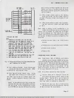
Refer to Fig. 1 for the location of the KTUs
in the 572A1 KSU and the location of maj or
components.
KEY TELEPHONE UNITS
2. 1 3
The KTUs employed in the 6 B KTS are all
8-inch SO-contact boards. All but the 488A
KTUs occupy a single-width
(3/4
inch) position.
The 488A KTUs require a double-width position.
The system options and method of application are
shown in Table
D.
Page 3
BSP 518-411-100-i01_1978-08-03.jpg Scanned by Fra n k Harrell, (Cowboy Frank) Castle Rock, Colorado Oct 15, 2012 20:55:35


