18
Installation SPIDER-SL
Release 06 01/2020
1.6
Pin assignments
1.7
Display elements
After the supply voltage is switched on, the device performs a self-test.
During this process, various LEDs light up.
1.7.1
Device state
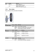
This LED provides information on the status of the power supply.
RJ45
Pin
10/100 Mbit/s
1000 Mbit/s
MDI mode
1
TX+
BI_DA+
2
TX
−
BI_DA
−
3
RX+
BI_DB+
4
—
BI_DC+
5
—
BI_DC
−
6
RX
−
BI_DB
−
7
—
BI_DD+
8
—
BI_DD
−
MDI-X mode
1
RX+
BI_DB+
2
RX
−
BI_DB
−
3
TX+
BI_DA+
4
—
BI_DD+
5
—
BI_DD
−
6
TX
−
BI_DA
−
7
—
BI_DC+
8
—
BI_DC
−
1
2
3
4
5
6
7
8
Содержание Hirschmann SPIDER SL Series
Страница 39: ...Installation SPIDER SL Release 06 01 2020 39 ...
Страница 40: ......

