32
EESX20 and EESX30
Release 1.5 04/2020
Bit
Signal name
Description
31…
24
n_SFP_Present_P[8..1]
Signal “SFP present” for FE-Ports 8..1 on Evaluation-Board;
low = SFP module is present / high = SFP module is not
present
23…
22
n_SFP_Present_G[2..1]
Signal “SFP present” for GE-Ports 2..1 on Evaluation-Board;
low = SFP module is present / high = SFP module is not
present
21
…
00
not used
Table 3-7: SPI received information (from a host system to the EESX module)
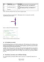
If the target application works without SPI
– GPIO expansion then it is necessary to connect the
SPI_MISO_Aux
signal as follows…
Figure 3-9: Alternative SPI implementation example
Table 3-8: Assembly information for alternative example
3.6 I2C Interface connection
For each Ethernet port there is one I2C bus connected to a SFP transceiver. This connection is only
required for the 100Base-FX mode in which a SFP transceiver is used. This interface can be used to read
transceiver status information, such as transceiver type, temperature, optical receive power and other
information provided by the selected SFP transceiver.
In addition, the I2C_Clk_x pins are used to pre-set the port mode during start-up. If a high level is
detected on the pin during start-up, the port will be set to fiber mode (100Base-FX), while the detection of
a low level will set the port to copper mode (10/100Base-TX). To set the I2C_Clk_x line to a high level,
connect a 4.7KOhm pull-up resistor to the VCC3.3 supply. Connect the I2C_Clk_x pin directly to GND for
TX mode.
3.7 Host Device connection over an Ethernet Interface
This chapter describes connecting the EESX module to a host device. The application is approved only
for port 6.
SPI_MISO
R111
Opt.
1
2
R110
Opt.
1
2
GND
VCC3.3


