background image

62

Configuring Your GV Node

Alarm Configuration

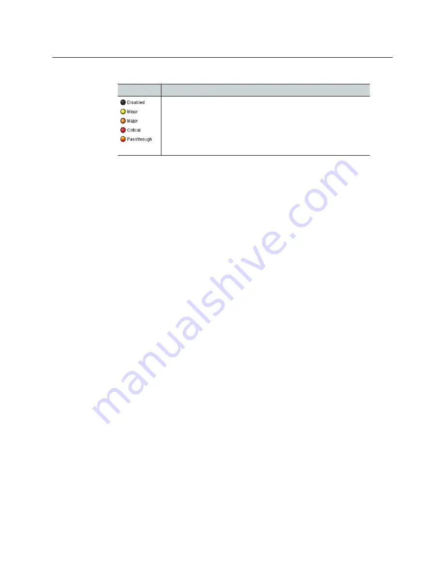
Levels associated with these alarms:

Icon & status Significance

The alarm makes no contribution (black icon)
The alarm is of minor importance (yellow icon)
The alarm is of major importance (orange icon)
The alarm is of critical importance (red icon)
The alarm exists but has no effect (used for text and composite 
alarms)

Shortcut:  if you click on 

Set All

 at the top of one of these columns, you will open a 

pulldown list that lets you assign a level to all alarms in that column simultaneously.

Once the alarms are configured, you may accept the changes or discard them.

Log Events

iControl maintains a log of alarm events associated with the card. The log is useful for 
troubleshooting and identifying event sequences. 

• Click in the checkboxes to enable logging of alarm events for each alarm individually. 

• Click the checkbox at the top of the column beside the card name to select all alarms.

At the bottom of the window are several other controls:

Copy to other cards

1 Click this button to open a panel that allows the alarm configuration set for this card to 

be copied into other cards of the same type.

2 Select one or more destination cards from the list in the window by clicking in the 

checkboxes, or all of them by clicking in the All checkbox.

3 Click 

Copy

 to start the copy process.

The Transfer Status window reports on the status of the data transfer.

Get alarm keys

Click this button to open a save dialog where you can save a file containing a list of all 
alarms on this card and their current values, along with an Alarm Key for each. The alarm 
keys are useful for system integration and troubleshooting. 

The file is saved in .csv format

OK, Apply, Cancel

OK

 accepts the settings and closes the window once the controller confirms that there 

are no errors.

Apply 

accepts the settings, but leaves the window open

Cancel

 closes the window without applying any changes, and leaves the previous 

settings intact.

Содержание grass valley GV NODE

Страница 1: ...User Manual M6103 9800 100 2016 07 15 GV NODE IP AGGREGATION PROCESSING AND EDGE ROUTING PLATFORM...

Страница 2: ...es to use their product manuals for their own internal business use Manuals for Grass Valley products may not be reproduced or transmitted in any form or by any means electronic or mechanical includin...

Страница 3: ...king any other equipment connections Identifies an external protective grounding terminal which may be connected to earth ground as a supplement to an internal grounding terminal Indicates that static...

Страница 4: ...id or aerosol cleaners use only a damp cloth Dangerous voltages may exist at several points in this equipment To avoid injury do not touch exposed connections and components while power is on High lea...

Страница 5: ...ctrostatic Discharge ESD Protection Electrostatic discharge occurs when electronic components are improperly handled and can result in intermittent failure or complete damage adversely affecting an el...

Страница 6: ...e bo tier de l quipement cette tension peut tre suffisante pour constituer un risque de d charge lectrique Avertit l utilisateur l op rateur ou le technicien de maintenance que des instructions import...

Страница 7: ...afin de ne pas endommager les connecteurs Coupez l alimentation avant de nettoyer l quipement Ne pas utiliser de nettoyants liquides ou en a rosol Utilisez uniquement un chiffon humide Des tensions d...

Страница 8: ...modules d alimentation auto adaptables v rifiez la configuration de chacun des modules d alimentation avant de les mettre sous tension Assurez une ventilation ad quate Pour viter toute surchauffe du p...

Страница 9: ...t ne remplacez la pile que par une pile du m me type recommand e par le fabricant Mettez les piles usag es au rebut conform ment aux directives du fabricant Avant de vous d faire de l quipement assure...

Страница 10: ...ay cause harmful interference to radio communications Operation of this equipment in a residential area is likely to cause harmful interference in which case the user will be required to correct the i...

Страница 11: ...572 2011 Grass Valley Grass Valley Technical explanations This statement is based on the information provided by our suppliers of components and collected through our Grass Valley s environmental mana...

Страница 12: ...xii Notices...

Страница 13: ...uration 11 Configure the Controller 11 Configure the Frame Reference 13 Configure the Fabric Module 13 2 Configuring Your GV Node 15 CPU ETH3 Controller User Interface 15 Identification 15 Status Moni...

Страница 14: ...ace 48 The iControl Service Panel 49 Identification 49 Status 51 Input Configuration SDI 52 Input Timing 55 Input Status 55 Output Configuration SDI 56 Output Timing 58 Output Status 59 GV Node Manage...

Страница 15: ...follows Installed in a rack Connected to your local IP network Registered to iControl Preliminary configuration completed for CPU ETH3 controller IFM 2T fabric module XIO 4901 SDI I O modular cards I...

Страница 16: ...ncorporates 12 40 GigE aggregation ports available on the rear panel These ports are accessed by 144 outputs and 144 inputs to the fabric card in order to interface multiple GV Nodes together via Poin...

Страница 17: ...TH 1 2 Dual GigE Ethernet ports for connection to external control systems e g iControl GV Convergent on RJ45 connectors ETH2 for future use MEDIA PORT GigE 10 GigE 1 2 Dual streaming ports for intern...

Страница 18: ...controller The two ports carry exactly the same signal The MON 2 output is placed near the modular card slots and could be connected to a Grass Valley SME 1901 Streaming Media Encoder located in slot...

Страница 19: ...rol panel provides a touch screen interface and is accessible through an aperture in the GV Node front door Local Control Panel Home screen The IP addresses of control ports ETH1 and ETH2 are displaye...

Страница 20: ...EL to access the next menu level When a parameter value is shown on the display modify the value by using the and buttons and then touch SEL to apply the value Touch ESC to go back to the previous men...

Страница 21: ...integrated frame reference the IFM 2T fabric module and the modular cards cannot be configured through this interface See Configure the Controller on page 11 for instructions on accessing and using th...

Страница 22: ...onfigure your GV Node Notes For detailed information about iControl refer to the iControl User Guide available from the Documentation Library section of Grass Valley s website Fordetailedinformationab...

Страница 23: ...lue unchanged Note Touching ESC when the input focus is in the first position returns you to the previous menu level 5 Once you have accepted all values in the desired address touch ESC repeatedly to...

Страница 24: ...nfiguration tab click Add The Target Information window opens 5 In Target Information enter the IP address that you have given your GV Node and a Densit name for the GV Node e g DNAME 6 Click OK The T...

Страница 25: ...ces make up the iControl presence of your GV Node GV Node Initial Configuration You will configure three elements of your GV Node in this initial setup Configure the Controller on page 11 Configure th...

Страница 26: ...vigation area The Time Date setup page appears If you have an NTP server s IP address enter it and select Enabled If you do not have an NTP server s IP address manually enter the current date and time...

Страница 27: ...ference module s iControl panel opens 2 To set the timecode and reference sources a Click the Input tab b In the Reference Source list select Auto c In the Timecode Source list select Auto Changes are...

Страница 28: ...V Node Manager associated with your GV Node and double click its icon The GV Node s GV Node Manager panel opens Note In the presence of multiple GV Node managers locate yours by checking the Comments...

Страница 29: ...e See CPU ETH3 Menu on page 63 for a complete listing of the local control menu Summary Identification 15 Status Monitoring 17 Network Settings 20 SNMP Functionality 21 Data Restoration 21 Factory Ali...

Страница 30: ...dentification FrameControllerDNAME Short Label 8 character short label used in iControl Frame Co Source ID Any text no text Comments Any text Densite Frame Service The remaining data boxes show manufa...

Страница 31: ...the data throughput of all cards installed in the frame In addition to the status displayed by the CTRL icon on the local control panel screen see page status information acquired by the controller c...

Страница 32: ...Monitoring Status Frame Select the Frame tab to see a report on the status of the frame s CPU fans and power supplies Status Network Select the Network tab to see a report on the status of the two Et...

Страница 33: ...nd Tx and receive Rx data rates and speed for all cards installed in the GV Node frame For a more detailed report on the status of a specific card open that card s control panel in iControl Status Adv...

Страница 34: ...name is the unique name by which this GV Node CPU ETH3 is known on the network The hostname should be 15 characters or less and may contain only the ASCII letters a through z case insensitive the digi...

Страница 35: ...o three target IP addresses can be entered in the menu via the SNMP OPTIONS item Data Restoration Many of the modular cards that can be installed in the GV Node frame are complex and have a lot of dat...

Страница 36: ...slot is the same type as the card that was there when the data was saved For automatic restore and save 1 Click the Restore Point button and view the Config tab Restore The CPU ETH3 can be set up to...

Страница 37: ...he Restore Points menu item Factory Alignment There may be times when the CPU ETH3 settings have been adjusted and it is useful to restore them to a normalized condition The CPU ETH3 controller mainta...

Страница 38: ...in these boxes to change the current setting If an automatic update via NTP is not enabled the clock will continue to run using an on board reference but precision is not guaranteed NTP IP address se...

Страница 39: ...ome screen status display and the status icon in the top left of the iControl window The alarms are reported to the iControl network and can be reported locally on the frame s GPI port GPI reporting c...

Страница 40: ...nel Using the Menu Access the Alarm Report menu item and scroll through the list of available alarms setting each to OFF or to report through GPI Use the GPI Report item to turn GPI reporting on or of...

Страница 41: ...select the reference source 1 Select the Input tab 2 Click the Reference Source pulldown 3 Click to select the reference source Selection Detail Auto Use the External reference if it s not available...

Страница 42: ...ame frame some cards can work in 25Hz frame rate and other cards in 29 97Hz The phase relation between these two frame rates will be arbitrary thus the name free run Timecode To select the timecode so...

Страница 43: ...reference all information extracted from the input is out of phase and the card may flag errors even if there are none To configure timecode logging 1 Select the Alarms tab 2 Select the checkboxes to...

Страница 44: ...mn b Click to select the appropriate alarm status from the drop down list All alarms in the column will be set to the selected status c Repeat steps a and b for the GSM contribution column 5 Click OK...

Страница 45: ...Short Label The short form label that iControl uses in some cases 8 characters Source ID A descriptive name for this frame reference Comments Any desired text The remaining data boxes show manufactur...

Страница 46: ...The LongID is the address of this frame reference in the iControl network Remote System Administration Opens the Joining Locators window which lists remote lookup services to which this frame referen...

Страница 47: ...42 Lane Statistics Reporting 43 Lane Statistics Reporting 43 Timing 44 Alarms 45 User Presets 46 Factory Configuration 47 Edge Device Control 48 In iControl Navigator or iControl Websites double clic...

Страница 48: ...rol applications Short Label The short form label that iControl uses in some cases 8 characters Source ID A descriptive name for this IFM 2T Comments Any desired text The remaining data boxes show man...

Страница 49: ...Joining Locators window which lists remote lookup services to which this IFM 2T is registered To add additional services 1 Click Add 2 Enter the IP address of a server running a Jini look up service u...

Страница 50: ...our GV Node Options When an error is flagged an error status message will be shown beneath the dashboard icons Multiple error messages will cycle in the display You can always check the current status...

Страница 51: ...option is active Port and Lane Configuration Each 40GbE port incorporates four 10GbE lanes and each of these can be configured individually Note The GV Node reserves bandwidth for each enabled lane s...

Страница 52: ...use the Enable All Lanes or Disable All Lanes checkboxes as a shortcut 3 Click Apply to confirm or Cancel to discard your changes To set the Source IP Address for each Lane 1 Click Global Config and...

Страница 53: ...ream destination address and port 1 Click TX Stream Config 2 Click on the tab corresponding to the 40GbE port whose transmit streams you want to configure 3 Enter a Stream Address and Stream Port for...

Страница 54: ...dress To set the Receive Stream source address and port 1 Click RX Stream Config 2 Click on the tab corresponding to the 40GbE port whose source streams you want to configure 3 Enter information for e...

Страница 55: ...dressing Utility 1 Click Global Config and select the Bulk Addressing tab 2 Use the pulldowns at the top to identify the range of Ports Lanes and Streams that you want to address 3 Click a radio butto...

Страница 56: ...in each of the twelve 40GbE ports 48 lanes in all can be viewed in the Lane Status panel To view the status of a lane 1 Click Lane Status panel 2 Select the tab for the 40GbE port containing the Lane...

Страница 57: ...r each of the 12 lanes 40GbE port 10GbE lane Tx Rx one row per lane not per stream for each Bandwidth Bytes throughput in Mbps Packets number of packets passed Error number of errors counted All dynam...

Страница 58: ...b 2 Select the Switching Alignment plane using the pulldown list Alignment Plane Details Module Slots Align on the SDI inputs from the XIO 4901 cards Aggregation Ports Align on the IP inputs from the...

Страница 59: ...s The fabric module generates alarms which are sent to the GV Node controller card when error conditions are detected These alarms are used to set the control panel status display and the status icon...

Страница 60: ...dow open or Cancel to discard the changes and close the window See Alarm Configuration on page 60 for a more detailed description of the contents of this panel User Presets The IFM 2T has 5 memory reg...

Страница 61: ...set of factory specified settings in memory and can be restored to that state at any time You can select which groups of parameters are restored To reset the IFM 2T to the factory default status 1 Cli...

Страница 62: ...rnal control of the RX streams Edge Device Control RX Stream Addressing Disabled RX stream addresses are static set in the RX Stream configuration page Enabled RX stream addresses are dynamically conf...

Страница 63: ...ntrol Service Panel Locate your XIO 4901 in iControl Navigator and double click its icon to open the service panel Identification The user can enter labels and comments to make this XIO 4901 easy to i...

Страница 64: ...ol applications Short Label The short form label that iControl uses in some cases 8 characters Source ID A descriptive name for this XIO 4901 Comments Any desired text The remaining data boxes show ma...

Страница 65: ...ning Locators window which lists remote lookup services to which this XIO 4901 is registered To add additional services 1 Click Add 2 Enter the IP address of a server running a Jini look up service us...

Страница 66: ...tion via the controller rear panel Green Ehernet OK Red Ethernet fault 6 Card health Green Card OK Red Card failure 7 Processing Mode Green Normal operation Yellow Test signal activated on at least on...

Страница 67: ...Use the Format pulldown to select one of these supported formats 525i 625i 1080p59 94A 1080p50A 1080i59 94 1080i50 720p50 To select the input format for all nine SDI Inputs at once 1 Click Input Confi...

Страница 68: ...ncel to leave the color unchanged To select the Output on Error for all nine SDI Inputs at once 1 Click Input Config and select the All tab 2 Click on the Output on Error Mode pulldown 3 Click to sele...

Страница 69: ...he the detection circuitry to lock it only to have the signal drift away from the reference unlocking the input circuits The lock unlock cycle will raise error messages and interfere with system opera...

Страница 70: ...the Name data box To select how the output format of the XIO 4901is determined 1 Click the Format Mode pulldown 2 Click to select the desired format mode Selection Details Follow source format The XI...

Страница 71: ...d a standard color bar to the SDI output RGB value Feed a full frame color patch to the SDI output To choose the color for the RGB value 1 Click the color patch in the screen beside the Output on Erro...

Страница 72: ...atch individually for each of the nine outputs as per To choose the color for the RGB value on page 54 You can use the color patches here instead of returning to the individual tabs they are interconn...

Страница 73: ...the Total Delay data window Output Status You can check the status of the nine SDI outputs by selecting Output Status GV Node Manager The GV Node Manager manages inputs and outputs between the IRM 2T...

Страница 74: ...rom the fabric module XIO 4901 The available choices depend on whether the MDX option is activated on the XIO 4901 card Alarm Configuration All modules with an iControl interface provide an Alarm Conf...

Страница 75: ...LED status is shown at the bottom of the alarm tree in the Status Name column This column is not shown in all cases Overall Alarm This column allows configuration of the contribution of each individua...

Страница 76: ...the column beside the card name to select all alarms At the bottom of the window are several other controls Copy to other cards 1 Click this button to open a panel that allows the alarm configuration...

Страница 77: ...63 GV Node User Manual Local Control Menus CPU ETH3 Menu Continued...

Страница 78: ...64 Configuring Your GV Node CPU ETH3 Menu...

Страница 79: ...umentation for these products available on the Grass Valley website www grassvalley com Setting Up iRouter for the GV Node The following procedure is a GV Node specific version of a broader procedure...

Страница 80: ...r for the GV Node The Router Manager Configurator window opens 3 Click the Physical Routers folder to open the physical routers management window on the right side of the panel 4 Click Add Router The...

Страница 81: ...ode into the Router host name IP address data box 9 Type 5194 in the UDP IP port data box 10 Click Add Level The Physical Level Configuration window opens 11 If you want to name the level differently...

Страница 82: ...red the GV Node as a physical router with a video level in iRouter Creating Logical Routers The next step in setting up iRouter to manage the GV Node is to establish a logical router or routers that r...

Страница 83: ...n a local phone number for the support center nearest you please consult the Contact Us section of Grass Valley s website www grassvalley com An online form for e mail contact is also available from t...

Отзывы: