MV-800 User Manual
Connecting Cables
MV-800 Hardware Installation 3.5
Issue 2 Revision 1
Page 39
© 2019 Grass Valley, a Belden Brand
3.5 Connecting Cables
Now that the MV-800 Integrated Multiviewer option hardware is installed, some connections
need to be made.
3.5.1 Connecting the Network and Multiviewer Display Output(s)
1.
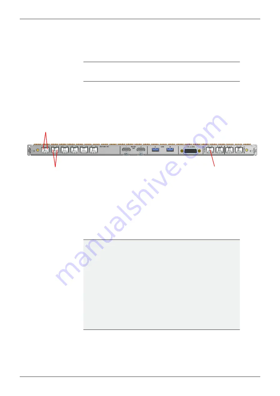
Connect the MV-800 Integrated Multiviewer directly to a computer network port via 1G
Ethernet port 1
(see Figure 23) using a standard CAT 5e Ethernet cable.
2.
Connect up to 4 display monitor screens to display output ports 1 to 4.
3.
If more display outputs have been licensed, then connect these.
4.
See the MV-8 Series Multiviewer user manual for details about configuring the MV-800
multiviewer using its RollCall templates.
Note:
The MV-800 Integrated Multiviewer must initially be configured from a
computer before being attached to the router’s IT network. See
RollCall Configuration Screens
Figure 231312 MV-800 Integrated Multiviewer Rear panel Connectors
1G Ethernet
Port 1
Multiviewer display
Outputs
1 and 2
Outputs
3 and 4
IMPORTANT
Ethernet connection:
Check the logical and physical connection of all Ethernet ports to the
MV-800 Integrated Multiviewer rear panel.
This is required for optimum MV-800 Integrated Multiviewer performance.
Explanation:
The MV-800 Integrated Multiviewer has more than one Ethernet
port with one IP address per Ethernet port.
However, even if a port is disconnected, its IP address can still be
“seen” through other the Ethernet ports.
This means the MV-800 can still
appear
to be operating normally,
i.e. with all Ethernet ports connected, even with one or more
unconnected network ports.
There is a MV-800 performance penalty for operating in this way.


