background image

11

HAZARDOUS (CLASSIFIED) LOCATION

UNCLASSIFIED LOCATION

EQUIPMENT

LOCATION

HAZARDOUS

NON

SEE NOTE 2

BA414DF or
BA418CF

SEE NOTE 5 & 6

BA414DF LOCATIONS:

Class I,  Division 1, Groups  A, B,C, D
Class II, Division 1, Groups  E, F & G
Class III
Class I, Zone 0, Group IIC

BA418CF LOCATIONS:

Class I,  Division 1, Groups  A, B,C, D
Class I, Zone 0, Group IIC

SEE 

NOTE 1

BA414DF and BA418CF

Terminals 1 & 2
These terminals comply
with the Intrinsically Safe
Concept (FISCO) defined by

IEC 60079-27
 Ui  = 17.5V           Uo = 0
 Ii = 380mA dc        Io = 0
 Pi = 5.32W            Po = 0
 Ci = 0
 Li = 8µH

and have the following 

Entity Parameters
Ui = 22Vdc      Uo = 0
Ii = 250mA       Io = 0
Pi = 1.2W       Po = 0

2

1

SEE NOTE 4

FIE

L

DBUS

SEE NOTE 8

SEE 

NOTE 9

equal to or less than

equal to or less than

equal to or greater than
equal to or greater than 

equal to or less than

The associated intrinsically safe barriers and fieldbus power supply must be FM
approved and the manufacturers’ installation drawings shall be followed when

The unclassified location equipment connected to the associated intrinsically safe
barriers and fieldbus power supply shall not use or generate more than 250V rms

Installation shall be in accordance with ANSI/ISA RP 12.06.01 “Installation of
Intrinsically Safe Systems for Hazardous (Classified) Locations” and the National

Fieldbus power supply with FISCO compliant output (IEC6009-27) or galvanic
isolator with entity parameters complying with the following requirements:

Electrical Code ANSI/NFPA 70.

Ca

4. 

3. 

Io or It

Uo or Vt

Po
La

installing this equipment.

or 250V dc.

2. 

Notes:

1. 

 Ci

 Li

Ii
Pi

Ui

cont:

supply must be CFM or CSA approved and the manufacturers’ installation drawings shall 

For installations in Canada the associated intrinsically safe barriers and fieldbus power 

be followed when installing the equipment.

Installations in Canada shall be in accordance with the Canadian Electrical Code C22.2

Содержание BA418CF-F

Страница 1: ...Supplied by Call us on 44 0 118 916 9420 Email info 247able com com Installation Maintenance Instructions BA418CF F ...

Страница 2: ...ark Danehill Lower Earley Reading Berkshire RG6 4UT UK Tel 44 0 118 9311188 Email info able co uk Aberdeen Office Unit 6 Airside Business Park Kirkhill Industrial Estate Dyce Aberdeen AB21 0GT UK Tel 44 0 1224 725999 Email ab able co uk Internet www able co uk e procurement www 247able com Registered in England No 01851002 VAT No GB 417 2481 61 ...

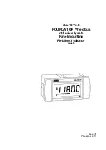
Страница 3: ...Issue 5 9th December 2011 BA418CF F FOUNDATION fieldbus Intrinsically safe Panel mounting Fieldbus Indicator Issue 5 ...

Страница 4: ...EMC 5 Maintenance 5 1 Fault finding during commissioning 5 2 Fault finding after commissioning 5 3 Servicing 5 4 Routine maintenance 5 5 Guarantee 5 6 Customer comments 6 Accessories 6 1 Scale marking 6 2 Tag number 6 3 Fieldbus Interface Guide 7 Index Appendix 1 FM Approval for use in the USA and cFM Approval for use in Canada Appendix 2 IECEx certification CONTENTS The BA418CF F is CE marked to ...

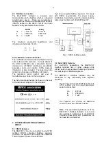
Страница 5: ...eb site www beka co uk System design information for FM cFM and IECEx is shown in separate appendices to this manual 2 INTRINSIC SAFETY CERTIFICATION 2 1 ATEX certificate The BA418CF F has been issued with an EC Type Examination Certificate by Notified Body Intertek Testing and Certification Ltd ITS confirming compliance with the European ATEX Directive 94 9 EC for Group II Category 1G gas atmosph...

Страница 6: ...rument adjacent to the terminals 3 SYSTEM DESIGN FOR HAZARDOUS AREAS 3 1 FISCO Systems The BA418CF F may be connected to any ATEX certified FISCO compliant fieldbus segment providing the segment can supply the additional 13mA required to power the instrument Fig 1 shows a typical fieldbus segment To comply with FISCO requirements the power supply terminators field devices and the interconnecting c...

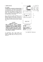
Страница 7: ...ve an IP66 seal between the instrument enclosure and the panel the smaller cut out must be used and the instrument secured with four panel mounting clips CAUTION Installation in Zone 0 When installed in a Zone 0 potentially explosive atmosphere requiring apparatus of Category 1G the indicator shall be installed such that even in the event of rare incidents an ignition source due to impact or frict...

Страница 8: ...ent enclosure and the panel c Connect the panel wiring to the rear terminal block as shown in Fig 3 To simplify installation the terminals are removable so that panel wiring can be completed before the instrument is installed Fig 3 Installation and terminal connections 4 3 EMC The BA418CF F complies with the requirements of the European EMC Directive 89 336 EEC For specified immunity all wiring sh...

Страница 9: ...onal mode 5 2 Fault finding after commissioning ENSURE PLANT SAFETY BEFORE STARTING MAINTENANCE Live maintenance is permitted on intrinsically safe equipment installed in a hazardous area but only certified test equipment should be used unless a gas clearance certificate is available If a BA418CF F fails after it has been functioning correctly the table shown in section 5 1 may help to identify th...

Страница 10: ... and a scale for the horizontal bargraph 6 2 Tag number The BA418CF F can be supplied with a thermally printed tag number on the rear panel adjacent to the terminals 6 3 Fieldbus Interface Guide The FOUNDATION fieldbus Interface Guide for Fieldbus Displays Fieldbus Indicators contains commissioning information for the BA418CF F A copy may be requested from the BEKA sales office or from the BEKA we...

Страница 11: ...eldbus Connection 2 3 Fig 3 Foundation 1 3 Guide 1 1 6 3 Firmware version number 5 1 FISCO 2 3 2 4 3 1 FM Approval Appendix 1 Function Blocks 1 Gas groups 2 2 Guarantee 5 5 IECEx Certification Appendix 2 Installation 4 Intrinsic safety 2 0 Appendices 1 2 Location 4 1 Appendices 1 2 Maintenance 5 Routine 5 4 Subject Section Notified Body 1 2 1 Servicing 5 3 Scale marking 6 1 Tag number 6 2 T rating...

Страница 12: ...ISCO Field Device requirements specified in IEC60079 27 The intrinsically safe system shown in Fig 1 of this manual may therefore be used for installations in the USA and Canada providing the fieldbus power supply terminators Zener barriers and galvanic isolators are FM Approved for US installations and CFM or CSA Approved for Canadian installations All installations must comply with BEKA associat...

Страница 13: ...dbus power supply must be FM approved and the manufacturers installation drawings shall be followed when The unclassified location equipment connected to the associated intrinsically safe barriers and fieldbus power supply shall not use or generate more than 250V rms Installation shall be in accordance with ANSI ISA RP 12 06 01 Installation of Intrinsically Safe Systems for Hazardous Classified Lo...

Страница 14: ...otection Crouse Hinds Myler hubs CHMG 50DT Metallic glands and hubs must be grounded see note 7 CMCXAA050 MCR050 MCX050 all metalic glands or conduit hubs must be connected together and grounded Killark Glands SSTG 1 STG 1 STAG 1 Any metallic or plastic cable gland or conduit hub that provides When installed in a hazardous classified location the BA414DF Fieldbus Indicators shall be fitted with ca...

Страница 15: ... isolation to ensure the intrinsically safety Fieldbus circuit remains passive The cable used to interconnect the devices needs to comply with the following parameters Loop resistance R 15 150 km Inductance per unit length L 0 4 1mH km Capacitance per unit length C 80 200nF km C C line line 0 5 C line screen if both lines are floating or C C line line C line screen if the screen is connected to on...

Страница 16: ... installations shall be in accordance with the National Electrical Code ANSI NFPA 70 The Nonincendive Field Wiring concept allows interconnection of Nonincendive Field Wiring Apparatus with Associated Nonincendive Field Wiring Apparatus using any of the wiring methods permitted for FM Approved Nonincendive Field Wiring Apparatus installed in the classified location with parameters complying with t...

Страница 17: ...eburred and clean Outside panel finish should be smooth free from particle inclusions runs or Minimum panel thickness should be Four panel mounting clips should be used To maintain IP66 protection between the BA418CF and the mounting panel 15 tightened to between 17 5 16 el cut out should be build up around cut out 4 Pan 14 Voc V OR 3B 531 Cont 20 and 22cNm 1 77 to 1 95 inLb 2 60 x 5 35 inches 0 0...

Страница 18: ...G 1 the required environmental protection Any metallic or plastic cable gland or conduit hub that provides The BA414DF and BA418CF Fieldbus Indicator enclosures In addition to the supplied bonding plate when 3 metallic glands or conduit hubs are fitted to BA414DF Fieldbus Indicators are manufactured from conductive plastic per Article 250 of the National Electrical Code the enclosures shall be gro...

Страница 19: ... Separately powered equipment needs galvanic isolation to ensure the intrinsically safety Fieldbus circuit remains passive The cable used to interconnect the devices needs to comply with the following parameters Loop resistance R 15 150 km Inductance per unit length L 0 4 1mH km Capacitance per unit length C 80 200nF km C C line line 0 5 C line screen if both lines are floating or C C line line C ...

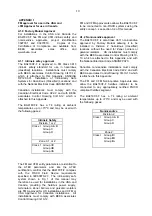
Страница 20: ...e BA418CF F may be installed in Zone 0 explosive gas air mixture continuously present Note Special conditions for safe use apply see above Zone 1 explosive gas air mixture likely to occur in normal operation Zone 2 explosive gas air mixture not likely to occur and if it does will only exist for a short time Be used with gases in groups Group A propane Group B ethylene Group C hydrogen Having a tem...

Отзывы: