background image

24

e.g. An indicator calibrated to display 0 to
10000, with a high alarm set at 9000 and
hysteresis of 200 will perform as follows:

High alarm will be activated when display
equals or exceeds 9000, but will not reset
until the display falls below 8800.

9.2.9 Alarm delay:   dELA

This function enables activation of the alarm
output to be delayed for a fixed time following
the alarm condition occurring. The delay can
be programmed in 1 second increments up to
3600 seconds. If a delay is not required zero
should be entered. To adjust the delay select
'dELA' from the alarm menu and press

P

which

will reveal the existing delay. Each digit of the
delay can be adjusted using the

Up

and

Down

push buttons, and the

P

button to move to the

next digit. When the required delay has been
entered, press 

to return to the alarm menu.

If the 'FLASH' function is activated the alarm
annunciator will flash until the delay time
expires, after which the alarm bar or column
will flash.

9.2.10

Alarm silence time:   SIL

This function is primarily intended for use in
small installations where the alarm output
directly operates an annunciator such as a
sounder. When the alarm silence time is set to
any figure other than zero, the

P

push button

becomes an alarm accept button.

After an

alarm has occurred, operating the

P

button will

cause the alarm output to revert to the non-
alarm condition for the programmed alarm
silence time.

The alarm annunciator(s) will

continue to indicate an alarm after it has been
accepted and silenced. The alarm silence time
may be adjusted between 0 and 3600 seconds
in 1 second increments.
To adjust the alarm silence time select 'SIL'
from the alarm menu and press

P

which will

reveal the existing time. Each digit can be
adjusted using the

Up

and

Down

push buttons,

and the

P

button to move to the next digit.

When the required time has been entered
press 

to return to the alarm menu.

If the 'FLASH' function is activated the alarm
bar or column will flash when the alarm occurs.
When the alarm is silenced by pushing the

P

button, the alarm bar or column will stop
flashing but the alarm annunciator will flash
until the alarm silence time expires.

9.2.11 Display alarm identification:

FLASH

The status of each alarm is always shown by
an alarm annunciator located above the digital
display. In addition to this annunciator, this
function provides an alarm warning on the
analogue bargraph display. When the function
is enabled and an alarm occurs, the setpoint
bar or column flashes. To check or change the
display alarm identification status select
'FLASH' from the alarm menu and press

P

to

reveal the current setting. The function can be
changed by pressing the

Up

or

Down

button

followed by the

E

button to return to the alarm

menu.

9.2.12 Access Setpoint:  AcSP

This function controls a separate menu which
provides direct access to the alarm setpoints
when the indicator is in the display mode, as
described in section 9.2.13

Thus allowing an

operator to adjust the alarm setpoints without
having access to the programme and alarm
menus. Further protection is provided by a
separate security code.
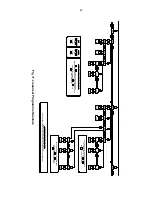
This direct access menu is enabled and a
separate security code entered from the 'AcSP'
function in the alarm programme menu shown
in Fig 14. To change the menu parameters
select 'AcSP' from the alarm programme menu
and press

P

which will display the enable

prompt 'EnbL'. Press

P

again to reveal if the

direct access menu is 'On' or 'OFF'. The

Up

or

Down

buttons will toggle the display between

the two conditions.
If 'OFF' is selected, the operator will not have
access to the setpoints from the display mode.
Return to the 'AcSP' prompt in the main menu
by pressing

 E

 twice.  

If 'On' is selected, the operator will have direct
access to the alarm setpoints from the display
mode via a separate optional security code.
To define the four digit numerical code press

P

to return to the 'Enbl' prompt followed by the

Up

or

Down

button to select the access code

prompt 'AcCd'.

Pressing

P

will reveal the

current security code. Each digit of the code
may be changed by operating the

Up

and

Down

push buttons, and the

P

button to move

to the next digit. When the required code has
been entered, press

E

twice to return to the

'AcSP' prompt in the Programme Menu.
Code 0000 will disable the security code
allowing direct access from the display mode
to the setpoints by pressing the

P

and

Up

buttons

simultaneously

when

the

AcSP

function is on.
New instruments with alarms are supplied with
this function disabled and the security code set
to 0000.

Содержание ba326c

Страница 1: ...rinsically safe loop powered analogue bargraph and digital indicator Issue 12 For instrument with serial numbers above 071235 01 001 Alarm setpoints Digital display Certification label Alarm annunciat...

Страница 2: ...ver and under range 7 Calibration Examples 7 1 Using an external current source 7 2 Using the internal references 8 Maintenance 8 1 Fault finding during commissioning 8 2 Fault finding after commissio...

Страница 3: ...ATEX Directive 2014 34 EU The EC Type Examination Certificate specifies that under fault conditions the output voltage current and power at input terminals 1 and 3 will not exceed those specified for...

Страница 4: ...y be installed in any of the European Economic Area EEA member countries ATEX certificates are also accepted for installations in Switzerland This manual describes installations which conform with EN6...

Страница 5: ...e incidents an ignition source due to impact or friction between the aluminium enclosure at the rear of the instrument mounting panel and iron steel is excluded 3 4 Certification label information The...

Страница 6: ...ated then two Zener barriers a two channel Zener barrier or a galvanic isolator must be used When the hazard is a IIC gas and two single channel Zener barriers or a two channel Zener barrier are used...

Страница 7: ...rast when viewed from directly ahead and slightly below the centre line of the instrument For reflective displays there is very little degradation of contrast when viewed from above the centre line bu...

Страница 8: ...AL and ALr2 Access to the programme menu is obtained by operating the P and E push buttons simultaneously If the instrument is not protected by a security code the first parameter root will be display...

Страница 9: ...ration See section 6 8 Display Description of function SEt Calibration of display using internal references Enables the zero and span of the digital indicator to be adjusted without the need for an ac...

Страница 10: ...On or OFF If set as required press E to return to the menu or press the Up or Down button to change the setting followed by the E button to return to the main menu 6 4 Display resolution rESn This fun...

Страница 11: ...11...

Страница 12: ...The indicator will display ZErO which is a request for a 4mA input current Adjust the external current calibrator to 4 000mA and again press P which will reveal the current zero display Each digit ex...

Страница 13: ...a password protected sub menu which allows the mains line frequency at which the indicator has maximum ac rejection to be selected and the two internal references to be calibrated To gain access to t...

Страница 14: ...internal references which should be periodically calibrated see section 6 10 2 6 12 Null display function null This function enables the BA326C analogue bargraph to operate as a deviation indicator di...

Страница 15: ...able functions can be obtained by moving the internal security link to the override position The original security code can then be viewed by selecting CodE from the main menu and pressing P To gain a...

Страница 16: ...or off by the Up or Down buttons Select OFF and press E to return to the main menu Step 4 Select frequency of max rejection Scroll though the main menu until Cond is displayed and press P The indicat...

Страница 17: ...ter the code and the first parameter root in the main menu will be displayed Step 2 Square root extractor With root displayed press P which will reveal the root extractor status The root extractor can...

Страница 18: ...ly display input has a voltage large ripple content Unable to Incorrect Enter correct enter the security security code or fit programme code security link in mode entered override position See Fig 9 8...

Страница 19: ...nstrument terminal block s by gently pulling and remove the rear panel which is secured by six screws see Fig 9 The electronic assembly may then be pulled out of the enclosure to reveal the display la...

Страница 20: ...menu provides direct access to both setpoints from the display mode without giving the operator access to the programme and alarm menus A different security code may be included to prevent tampering o...

Страница 21: ...ctance specified by the system certificate of the circuit connected to each alarm Fig 13 Typical alarm application 9 2 3 Programming and adjustment When an alarm card is added to a BA326C the main pro...

Страница 22: ...section 9 2 12 9 2 4 Alarm enable EnbL This function allows the alarm to be enabled or disabled without altering any of the alarm parameters To check or change the function select EnbL from the alarm...

Страница 23: ...using the Up and Down push buttons and the P button to move to the next digit When the required hysteresis has been entered press E to return to the alarm menu Fig 14 Alarm Programme Menu P P E ALr2 E...

Страница 24: ...1 Display alarm identification FLASH The status of each alarm is always shown by an alarm annunciator located above the digital display In addition to this annunciator this function provides an alarm...

Страница 25: ...t may be adjusted using the Up and Down push buttons and the P button to move to the next digit When the required setpoint has been entered pressing E will return the display to the SP1 or SP2 prompt...

Страница 26: ...ect CAL from the main menu and press P to enter the Add function press P again to reveal the current and total number of break points Each subsequent operation of the P push button will introduce an a...

Страница 27: ...the Add function described above When the required number of break points has been entered return to the sub menu by pressing E The indicator will display Add or dEL depending upon the last function u...

Страница 28: ...er input current at which each break point and to move to next digit P Enter requied display at each break point by pressing or and and to move to next digit P Calibration using internal references Wi...

Страница 29: ...nd inductance of the display backlight is Ci 30nF Li 10 H To determine the maximum permissible cable parameters the equivalent backlight parameters must be subtracted from the maximum cable capacitanc...

Страница 30: ...tions for safe use apply when installed in Zone 0 These are explained below WARNING installation in Zone 0 When installed in a Zone 0 potentially explosive atmosphere the indicator shall be installed...

Отзывы: