background image

GN-9371_2_3 User Manual 


Page  27  of (110) 

G-series GN-9371_2_3 PIO Rev. 1.02.docx 

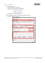
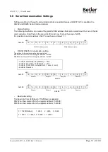
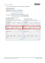
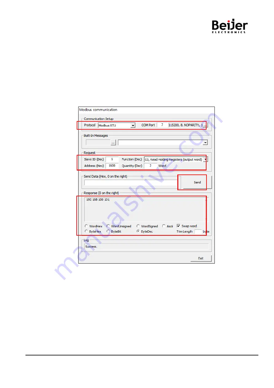
(2)  Write the value of each. 

*Protocol : Modbus TCP, Modbus RTU 
*ComPort : User Port / Baudrate : 115200(default) 

*Address(Hex) : 1600 (IP Address Register)     

:

: 1602 (IP Subnet Mask Register) 

:

:

:

1604 (Gate way Register) 

:

:

:

1610 (Mac Address Register) 

*Function(Dec) : 03, Read Holding Registers 


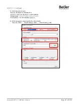
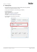
(3)  After clicking the ‘send’ button and confirm the necessary information. 

If you choose 'ByteDec', easier to see. 


Содержание GN-9273

Страница 1: ...Page 1 of 110 G series GN 9371_2_3 PIO Rev 1 02 docx Programmable IO GN 9371 GN 9372 GN 9273 User manual...

Страница 2: ...l Page 2 of 110 G series GN 9371_2_3 PIO Rev 1 02 docx DOCUMENT CHANGE SUMMARY REV PAGES REMARKS DATE Editor 1 01 First release 2019 05 13 NJL CSM 1 02 64 8 1 Source download and upload GN 9372 GN 937...

Страница 3: ...nical Setup 18 5 1 How to mount on Din Rail 18 5 2 How to dismount on Din Rail 18 5 3 Removable Terminal Block RTB 19 5 4 Method of Wiring 19 6 G Series PIO Programmable I O Functions 20 6 1 Connectio...

Страница 4: ...Coils 82 A 3 2 0x02 Read Discrete Inputs 83 A 3 3 0x03 Read Holding Registers 84 A 3 4 0x04 Read Input Registers 85 A 3 5 0x05 Write Single Coil 86 A 3 6 0x06 Write Single Register 87 A 3 7 0x08 Diagn...

Страница 5: ...t assemble the products and wire with power applied to the system Else it may cause an electric arc which can result into unexpected and potentially dangerous action by field devices Arching is explos...

Страница 6: ...uccessful application and understanding of the product Identifies information about practices or circumstances that can lead to personal injury property damage or economic loss Attentions help you to...

Страница 7: ...connection to different field bus systems can be established by each of the corresponding Network Adapter Module e g for MODBUS TCP Ethernet IP EtherCAT PROFINET CC Link IE Field PROFIBUS CANopen Devi...

Страница 8: ...module may have 3 types of data as I O data configuration parameter and memory register The data exchange between network adapter and expansion modules is done via an I O process image data by intern...

Страница 9: ...le series Refer to IO Module s Specification Max Current Field Power Contact DC 10A Max Weight 167g Module Size 54mm x 99mm x 70mm Environment Condition Operating Temperature 20 60 UL Temperature 20 6...

Страница 10: ...sualization Not Supporting only GN 9373 Max Task 10 Max Cycle Task 10 Max Status Task 10 Process Time 90 Instructions 1usec 7usec RTC Retain Time 15 days Accuracy 2min per a month Interface Specificat...

Страница 11: ...73 Network Variable GN 9371 72 73 Modbus TCP Master GN 9371 72 73 5 Modbus TCP Slaves can be connected Modbus TCP Slave GN 9371 72 73 16 Modbus TCP Masters can be connected Web Server GN 9371 72 73 16...

Страница 12: ...nual Page 12 of 110 G series GN 9371_2_3 PIO Rev 1 02 docx 4 Module Description 4 1 GN 9371 72 73 MODBUS Programmable I O The modules are not hot swappable It means that they should be not removed in...

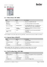
Страница 13: ...n self testing Firmware fault The IP address to access IAP web server during IAP Mode 192 168 100 10 Recommended to use FireFox 4 2 2 Network Status LED NET State LED is To indicate Off line Off Netwo...

Страница 14: ...n Run Exchanging IO Green Exchanging I O data Connection Fault during Exchanging IO Blinking Red One or more expansion module occurred in fault state Check the expanded module configuration Failed the...

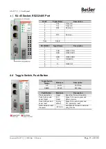
Страница 15: ...TXD 3 RXD RS232 RXD 4 5 GND RS232 GND 6 D RS 485 D 7 8 D RS485 D 9 Toggle Switch Status Module is Description UP RUN PLC Run DOWN STOP PLC Stop Push Button Module is Description Press and detach Reset...

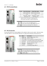
Страница 16: ...eld power pins Do not touch data and field power pins in order to avoid soiling and damage by ESD noise To prevent ESD noise it is recommended to use the END module Pin No Signal Description Signal De...

Страница 17: ...GN 9371_2_3 User Manual Page 17 of 110 G series GN 9371_2_3 PIO Rev 1 02 docx 4 7 Dimension mm...

Страница 18: ...smount on Din Rail As above figure in order to safeguard the FnIO module from jamming it should be fixed onto the DIN rail with locking level To do so fold on the upper of the locking lever To pull ou...

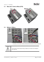
Страница 19: ...2_3 PIO Rev 1 02 docx 5 3 Removable Terminal Block RTB 5 4 Method of Wiring Connecting or removing the cable by pushing the terminal button for the relevant points The use of an incorrect supply volta...

Страница 20: ...p and configuration for the PIO is available via the IO Guide Pro And user can set up the IP Address RTC from the Webserver page 6 1 Connection to IO Guide Pro by Modbus RTU RS 232 or RS 485 1 Install...

Страница 21: ...21 of 110 G series GN 9371_2_3 PIO Rev 1 02 docx 4 After creating a project and Click the Automatic scan Icon 5 Write the value Port Node Baudrate and Click the Scan button 6 After the end to scan the...

Страница 22: ...GN 9371_2_3 User Manual Page 22 of 110 G series GN 9371_2_3 PIO Rev 1 02 docx 7 Now ready to use the IO Guide Pro with RTU...

Страница 23: ...110 G series GN 9371_2_3 PIO Rev 1 02 docx 6 2 Connection to IO Guide Pro by Modbus TCP 1 Open the IO Guide Pro Tool and Click the New project Icon Same as RTU 2 Write the Project Name Select the Bus...

Страница 24: ...ser Manual Page 24 of 110 G series GN 9371_2_3 PIO Rev 1 02 docx 3 After creating a project and click the Automatic Scan Icon 2 Click the Scan button 4 After the end to scan the network Click the OK b...

Страница 25: ...GN 9371_2_3 User Manual Page 25 of 110 G series GN 9371_2_3 PIO Rev 1 02 docx 5 Now ready to use the IO Guide Pro with Modbus TCP...

Страница 26: ...rated by three dots Subnet Mask A subnet mask is a number that defines a range of IP addresses that can be used in a network It is not something you wear on your head to keep subnets out Subnet masks...

Страница 27: ...Modbus RTU ComPort User Port Baudrate 115200 default Address Hex 1600 IP Address Register 1602 IP Subnet Mask Register 1604 Gate way Register 1610 Mac Address Register Function Dec 03 Read Holding Re...

Страница 28: ...atically This is usually done in the bootstrap process of computers or operating systems running on them The BOOTP server can assign the IP address from a pool of addresses to each client DHCP set of...

Страница 29: ...the value of each Protocol ModbusTCP Modbus RTU ComPort User Port Baudrate 115200 default Address Hex 160B IP Setting Method Register Function Dec 16 Write Multiple registers 2 Write the register valu...

Страница 30: ...gn the IP Address manually via the CREVIS Bootp Server in IO Guide Pro Default IP Address is 192 168 1 50 1 Run Crevis IOGuidePro Bootp Server GN 9371 2 3 can support DHCP or Bootp If DHCP server is w...

Страница 31: ...n the GN 9371 2 3 and Click the Start Bootp button 3 Double Click MAC address of GN 9371 2 3 Turn on the power of GN 9371 2 3 and Bootp server will retry to get the MAC address or IP address 2 times f...

Страница 32: ...9371_2_3 User Manual Page 32 of 110 G series GN 9371_2_3 PIO Rev 1 02 docx 4 Set the IP and click OK 5 Finish Subnet Mask and Gateway is assigned automatically by the value that is set in the compute...

Страница 33: ...Modbus station RS232 RS485 Communication setting The options for the communication can be selected RS232 can be selected from the register address 0x1606 RS485 can be selected from the register addres...

Страница 34: ...ex 1606 RS232 Baud rate Register 1607 RS232 Use bit Setting Register 1608 RS485 Baud rate Register 1609 RS485 Use bit Setting Register Function Dec When the value is write 16 Write Multiple registers...

Страница 35: ...setup of EEPROM All expansion slot configuration parameters are cleared 1 Run Crevis IOGuidePro Protocol Messenger Modbus 2 Write the value of each Protocol Modbus RTU ComPort User Port Baudrate 1152...

Страница 36: ...the Register also can be read 1 Run Crevis IOGuidePro Protocol Messenger Modbus 2 Write the value of each Protocol Modbus TCP Modbus RTU ComPort User Port Baudrate 115200 default Address Hex 1620 RTC...

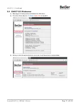
Страница 37: ...9371_2_3 PIO Rev 1 02 docx 6 9 GN 9371 2 3 Webserver 1 Main page is showing various information for PIO status 2 To access the webserver IP Address setup htm is required 3 When you click the expansio...

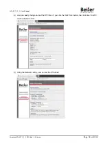
Страница 38: ...38 of 110 G series GN 9371_2_3 PIO Rev 1 02 docx 4 User can easily change and set the RTC time If you click the Get Time button the clock time from PC will be adapted to PIO 5 Using the Network settin...

Страница 39: ...get the IP address After power on the PIO and push the Reset switch in front of PIO The switch should be pushed for 20 seconds at least PIO will be fall into the factory default mode All of PIO LED wi...

Страница 40: ...compatible with PIO The library of V3 5 11 3 need to be used to the latest version if user want to use the latest CODESYS version Unzip the downloaded file and Installation Setup_CODESYSV35SP11Patch3...

Страница 41: ...GN 9371_2_3 User Manual Page 41 of 110 G series GN 9371_2_3 PIO Rev 1 02 docx Please check whether they are installed correctly or not...

Страница 42: ...110 G series GN 9371_2_3 PIO Rev 1 02 docx 7 2 2 Created Project 1 Run the CODESYS program 2 File New Project select Standard project Write the Project Name Location Click OK 3 Select Device GN 9371 2...

Страница 43: ...face 7 2 4 Setup I O 1 Additional Device Click on the model you want to use and click Plug Device For the normal operation you must select the module image in order through the CODESYS like the user c...

Страница 44: ...ect Parameter setting Click Digital IOs Configuration The setting unit of the parameter is bytes IO Mapping Click Digital IOs I O Mapping If there are no set values in the red square you can program t...

Страница 45: ...vice Click Device GN 9371 2 3 right click Click Add Device 2 Add Ethernet Adapter Click Fieldbus Ethernet Adapter Ethernet and Add Device Click 3 Add Device after Selecting Ethernet and Add MODBUS TCP...

Страница 46: ...se the continuously without disconnection it should be checked the auto reconnect 4 Add Device after adding MODBUS TCP Master and Add Modbus TCP Slave Click Modbus_TCP_Master right click Click Add Dev...

Страница 47: ...N 9371_2_3 PIO Rev 1 02 docx 5 Configuration of the ModbusTCP Slave Click Modbus_TCP_Slave Modbus TCP Slave Write Slave IP Address GN 9371 2 3 Click Modbus Slave Channel Add a channel of GN 9371 2 3 a...

Страница 48: ...Add Device Click Device GN 9371 2 3 right click Click Add Device 2 Add Ethernet Adapter Click Fieldbus Ethernet Adapter Ethernet and Add Device Click 3 Add Device Modbus TCP Slave Click Ethernet righ...

Страница 49: ...e out check box When the time out box checked the Modbus slave mapped data from master will be retained for set time ms After exceed the time out all of the Modbus slave mapped data will be cleared fo...

Страница 50: ...rk Variable List Sender You have to add one more devices in the devices tree 2 Define the network properties of the sender GVL You have to select UDP as network type List identifier and Node ID is the...

Страница 51: ...Rev 1 02 docx 4 Created by Global Variables 5 It is possible to create a program using a global variable in prog_sender in the sender application enter the following use of variable iglobvar in prog_...

Страница 52: ...Communication Settings click Scan network After completing the search double click the Gateway icon to make it activated Add device TCP Device Communication Settings click Add device After write the I...

Страница 53: ...al Page 53 of 110 G series GN 9371_2_3 PIO Rev 1 02 docx 7 6 OPC Server GN 9372 GN 9373 only 1 Add Object for the Symbolic Configuration to Application Project 2 Define the Symbolic variable to config...

Страница 54: ...defined variable will appear in order to activate the OPC server User can set this variable to be exposed to outside as OPC variable in use click the radio button on it 4 In order to set the OPC confi...

Страница 55: ...x 5 To use the OPC server variable at outside of PIO user should set the OPC configurator Click the OPC configurator in the windows menu OPC Configurator Tool Supported by 32bits OPC Configurator Tool...

Страница 56: ...s gateway the Port number should be 1217 8 TCP mode OPC configuration setting If it is operated with TCP IP mode check the Use TCP IP blockdriver tap and put the PLC IP address Set the PIO IP address...

Страница 57: ...Function block 0x8002 RS232 RS485 Enable at the same time for CODESYS Function block RTU Master User can set the RS 232 or 485 by using IO Guide Pro or Modbus communication tool Address value RS232C p...

Страница 58: ...number Baud rate parity Data Bits Stop Bit and so on in Modbus Com configuration tap By choosing the COM port number RTU type can be decided from CODESYS Tool COM Port 1 RS 232 Set up available COM Po...

Страница 59: ...9371_2_3 PIO Rev 1 02 docx 5 Set the Response Timeout and Time between frames at the Modbus_Master_COM_Port configuration tap It does not support the ASCII mode in PIO 6 Add the device of Modbus_Slav...

Страница 60: ..._2_3 PIO Rev 1 02 docx 7 Set the Slave Address Number and Response Timeout at the Modbus_Slave_COM_Port configuration tap 8 At the Modbus Slave Channel Tap user can set the Modbus Address 9 Below is t...

Страница 61: ...ualization GN 9373 only 1 Add Web Visualization manager to Application project 2 Set the Web Visualization option on the Web Visualization manager User should set the Start Visualization path and can...

Страница 62: ...GN 9371_2_3 User Manual Page 62 of 110 G series GN 9371_2_3 PIO Rev 1 02 docx 4 Set the Visualization Manager should be 3 5 9 0 5 Make the Web visualization page...

Страница 63: ...ls No 2 View Tools available visualization elements No 3 View Properties configuration editor for the visualization element currently selected in the editor area No 4 Menu Visualization commands for w...

Страница 64: ...g project source code to a PLC as a project archive User can then transfer this project archive back to the development system from the PLC as needed Requirement The connection settings are configured...

Страница 65: ...ev 1 02 docx 9 SNTP 1 Route Device Parameters 2 Enable the SNTP Service IP Address of First SNTP Server PC IP Address 3 The current time will change in order to be same as the server time Current Time...

Страница 66: ...GN 9371_2_3 User Manual Page 66 of 110 G series GN 9371_2_3 PIO Rev 1 02 docx 5 CODESYS Program...

Страница 67: ...he generic device editor It lists the events that were recorded on the target system This concerns Events during the startup and shutdown of the system components loaded with version Application downl...

Страница 68: ...YS establishes the connection automatically to the PLC for the duration of the file transfer User can copy files to and from the local file system and the controller Requirement The vendor has unlocke...

Страница 69: ...s save location and format in the object Recipe Manager Insert one or more recipe definitions below this object A recipe definition comprises one or more recipes for the contained variable The recipe...

Страница 70: ...GN 9371_2_3 User Manual Page 70 of 110 G series GN 9371_2_3 PIO Rev 1 02 docx...

Страница 71: ...the recipe definition 1 you define different value sets for the variables which are termed recipes 2 User can toggle the display of the recipe definition between the flat list view 3 and the structur...

Страница 72: ...GN 9371_2_3 User Manual Page 72 of 110 G series GN 9371_2_3 PIO Rev 1 02 docx User can save the Recipe about their valued variables...

Страница 73: ...e executed first within the task cycle Then data recording starts with value storage including time stamps These time stamps are relative and refer to the start time of the data recording The data yie...

Страница 74: ...GN 9371_2_3 User Manual Page 74 of 110 G series GN 9371_2_3 PIO Rev 1 02 docx...

Страница 75: ...riable values You can also set data breakpoints to halt program execution when the value of a specific variable changes CODESYS supports breakpoints in all IEC editors The halt at a breakpoint or data...

Страница 76: ...ts online user management This command opens the Add Online User dialog box where you define the login data of the new user Please use a strong password as follows Password length 8 characters best 12...

Страница 77: ...P over Ethernet 1 Apply a power with pushing a reset button Mod LED will blink Green Red 2 Execute Firefox It is recommended to using Firefox 3 Connect to 192 168 1 51 and login User ID Beijer Electro...

Страница 78: ...GN 9371_2_3 User Manual Page 78 of 110 G series GN 9371_2_3 PIO Rev 1 02 docx 6 If it finish you can see a below message Update Firmware Done And click a Reset Adapter button...

Страница 79: ...is red Wrong address ID Occurrence critical error in firmware Contact Sales team and send module for repair I O LED turns off Failure of realization expansion Module None expansion Module Check conne...

Страница 80: ...Terminator resistor If terminator resistor is not installed install terminator resistor Check location of terminator resistor Configuration of Node address Check duplication node address Configuration...

Страница 81: ...area is addressable by bit address Size of input image bit is size of input image register 16 2 0x0800 Read Write Process output image bits All output registers area is addressable by bit address Siz...

Страница 82: ...te one word output Unicast Broadcast 8 0x08 Diagnostics Serial Line only Read diagnostic register Unicast 15 0x0F Write Multiple Coils Write a number of output bits Unicast Broadcast 16 0x10 Write Mul...

Страница 83: ...uts In the PDU Discrete Inputs are addressed starting at zero Therefore Discrete inputs numbered 1 16 are addressed as 0 15 The discrete inputs in the response message are packed as one input per bit...

Страница 84: ...bits and the second contains the low order bits Request Field name Example RTU Start of Frame t1 t2 t3 Slave Address 0x07 0x07 Function Code 0x03 0x03 Starting Address Hi 0x08 0x08 Starting Address Lo...

Страница 85: ...s and the second contains the low order bits Request Field name Example RTU Start of Frame t1 t2 t3 Slave Address 0x07 0x07 Function Code 0x04 0x04 Starting Address Hi 0x00 0x00 Starting Address Lo 0x...

Страница 86: ...not affect the output Request Field name Example RTU Start of Frame t1 t2 t3 Slave Address 0x07 0x07 Function Code 0x05 0x05 Starting Address Hi 0x10 0x10 Starting Address Lo 0x01 0x01 Quantity of Out...

Страница 87: ...Frame t1 t2 t3 Slave Address 0x07 0x07 Function Code 0x06 0x06 Starting Address Hi 0x08 0x08 Starting Address Lo 0x00 0x00 Quantity of Outputs Hi 0x11 0x11 Quantity of Outputs Lo 0x22 0x22 Error Chec...

Страница 88: ...0x00 Data Hi 0x11 0x11 Data Lo 0x22 0x22 Error Check CRC LRC 0x6C 0x24 End of Frame t1 t2 t3 Sub function 0x0000 0 Return Query Data The data passed in the request data field is to be returned looped...

Страница 89: ...uest Data Field Response Description 0x000D 13 0x0000 Exception Error Count Sub function 0x000E 14 Return Slave Message Count The response data field returns the quantity of messages addressed to the...

Страница 90: ...quest Field name Example RTU Start of Frame t1 t2 t3 Slave Address 0x07 0x07 Function Code 0x0F 0x0F Starting Address Hi 0x10 0x10 Starting Address Lo 0x00 0x00 Quantity of Outputs Hi 0x00 0x00 Quanti...

Страница 91: ...ion Code 0x0F 0x0F Starting Address Hi 0x08 0x08 Starting Address Lo 0x00 0x00 Quantity of Registers Hi 0x00 0x00 Quantity of Registers Lo 0x02 0x02 Byte Count 0x04 0x04 Register Value 0 Hi 0x11 0x11...

Страница 92: ...RTU Start of Frame t1 t2 t3 Slave Address 0x07 0x07 Function Code 0x17 0x17 Read Starting Address Hi 0x08 0x08 Read Starting Address Lo 0x00 0x00 Quantity of Read Hi 0x00 0x00 Quantity of Read Lo 0x0...

Страница 93: ...00 4096 Address Access Type Size Description 0x1000 4096 Read 1 word Vendor ID 0x02E5 741 Crevis Co Ltd 0x1001 4097 Read 1 word Device type 0x000C Network Adapter 0x1002 4098 Read 1 word Product Code...

Страница 94: ...then 0x9372 0x1110 4368 Read 1word Number of expansion slot 0x1111 4369 Read 1word Number of active slot 0x1112 4370 Read 1word Number of inactive slot 0x1113 4371 Read Up to 64 words Expansion slot M...

Страница 95: ...1 nibble Data bit 0 8bit default 1 9bit 2 nibble Stop bit 0 1bit default 1 2bit 3 nibble Parity bit 0 none default 1 odd 2 even 4 nibble Reserve 0x160A 5642 Read Write 1word MODBUS Station High 1byte...

Страница 96: ...2320 8992 0x233F 9023 Slot 27 0x2340 9024 0x235F 9055 Slot 28 0x2360 9056 0x237F 9087 Slot 29 0x2380 9088 0x239F 9119 Slot 30 0x23A0 9120 0x23BF 9151 Slot 31 0x23C0 9152 0x23DF 9183 Slot 32 0x23E0 918...

Страница 97: ...0x202D 8237 0x204D 8269 0x27AD 9133 0x27CD 9165 0x0E 14 0x200E 8206 0x202E 8238 0x204E 8270 0x27AE 9134 0x27CE 9166 0x0F 15 0x200F 8207 0x202F 8239 0x204F 8271 0x27AF 9135 0x27CF 9167 0x10 16 0x2010...

Страница 98: ...2 2 Read 1word Input start register address of input image word this slot 0x03 3 Read 1word Input word s bit offset of input image word this slot 0x04 4 Read 1word Output start register address of out...

Страница 99: ...og Input Ch2 high byte Slot 3 Analog Input Ch2 low byte Slot 3 0x0005 Analog Input Ch3 high byte Slot 3 Analog Input Ch3 low byte Slot 3 0x0006 Discrete In high 8pts Slot 4 Discrete In low 8pts Slot 4...

Страница 100: ...In 4pts Slot 5 Discrete In 4pts Slot 1 Input Assembly Priority 1 Analog Input Data Word type 2 8 or 16 points Discrete Input Data Byte type 3 4 points Input Data Bit type 4 2 points Input Data Bit ty...

Страница 101: ...6 Discrete In high 8pts Slot 4 0x0010 Discrete In 4pts Slot 7 Discrete In 4pts Slot 5 Discrete In 4pts Slot 1 S Series uses the byte oriented register mapping Size of input image bit is size of input...

Страница 102: ...essed Output Processing Data Addr 15 14 13 12 11 10 9 8 7 6 5 4 3 2 1 0 0x0800 Analog out Ch0 high byte Slot 3 Analog out Ch0 low byte Slot 3 0x0801 Analog out Ch1 high byte Slot 3 Analog out Ch1 low...

Страница 103: ...GT 22CA 32 Points Source 24Vdc 0 3A 40P connector 22CA 15 GT 2618 8 Points Sink 24Vdc 2A 10RTB 2618 16 GT 2628 8 Points Source 24Vdc 2A 10RTB 2628 17 GT 2734 4 Points MOS Relay 240Vdc ac 0 5A 10RTB 27...

Страница 104: ...dc 12Bits 10RTB 3924 48 GT 3944 4 Channels Differential 0 5 0 10 5 10Vdc 16Bits 10RTB 3944 49 GT 3928 8 Channels Differential 0 5 0 10 5 10Vdc 12Bits 18RTB 3928 50 GT 3948 8 Channels Differential 0 5...

Страница 105: ...52 2CH Synchronous Serial Interface Input 10RTB 5352 72 GT 5521 1CH Stepper Module TBD 5521 Power Module 73 GT 7408 Shield Module 7408 74 GT 7508 Common for 0Vdc 7508 75 GT 7511 Power Expansion In 24V...

Страница 106: ...ctly for as below address This address can be access able at Modbus RTU slave as well Address IEC Address Contents 0x0000 0x07FF IW0 IW2047 2048 words Input and Internal memory Area is write protected...

Страница 107: ...er Manual Page 107 of 110 G series GN 9371_2_3 PIO Rev 1 02 docx Set the station IP address for PIO Slave Read the 30000 address for the PIO slave input address Read Write the 40800 for the PIO slave...

Страница 108: ...The modebusRTU slave will be access to CODESYS address directly for as below address Address IEC Address Contents 0x0000 0x07FF IW0 IW2047 2048 words Input and Internal memory Area is write protected...

Страница 109: ...02 docx Read the 30000 address for the PIO slave input address Read Write the 40800 for the PIO slave output address It is same as other CREVIS Modbus slave system address These example are for using...

Страница 110: ...GN 9371_2_3 User Manual Page 110 of 110 G series GN 9371_2_3 PIO Rev 1 02 docx Head office Beijer Electronics AB Box 426 20124 Malm Sweden Phone 46 40 358600 www beijerelectronics com...

Отзывы: