BEGA Gantenbrink-Leuchten KG · Postfach 31 60 · 58689 Menden · [email protected] · www.bega.com
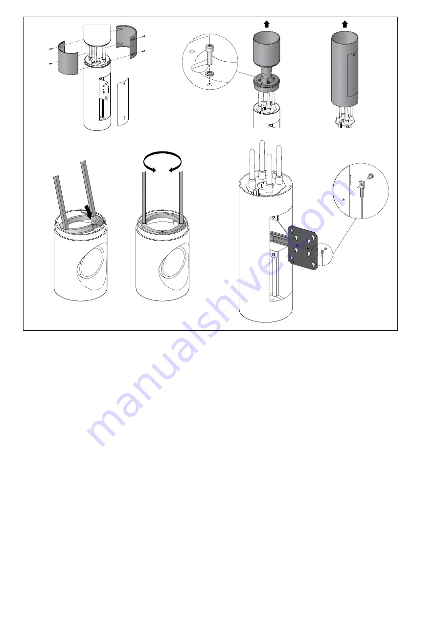
Antennen- / WiFi-Segment montieren
Antennensegment vor Befestigung auf
Lichtmast demontieren.
Innensechskantschrauben (SW 4) lösen und
Abdeckschalen abziehen.
Beide Innensechskantschrauben (SW 7)
herausdrehen und zunächst das obere,
danach das untere Rohrsegment abheben.
Spannring mit Antenneneinheit – wie in
der Skizze dargestellt – in die Mastöffnung
einsetzen und so ausrichten, das sich der
herausziehbare Geräteträger auf der gleiche
Achse mit den beiden unteren Türen befindet.
Verschluss der Montagetür entriegeln und
Montagetür herausnehmen.
Unteres Rohrsegment über die Antenneneinheit
führen und so ausrichten, dass sich der Geräte-
träger aus der Türöffnung herausziehen lässt.
Oberes Rohrsegment über die Antennen führen
und mit den beiden Innensechskantschrauben
(SW 7) fest verschrauben.
Anzugsdrehmoment = 12 Nm.
Bauseitiges WiFi-Modul mit beiliegenden oder
anderen geeigneten Befestigungsschrauben
am Geräteträger befestigen.
Beim Anschluss der 4 Antennenleitungen
unbedingt auf richtige Belegung achten.
Es müssen immer 2 gegenüberliegende
Antennen (blau + blau bzw. grün + grün)
zusammen verschaltet werden.
Schutzleiter / Funktionserde am Access
Point sowie an der C-Schiene im unteren
Mastbereich anschließen.
Ringöse vom Sicherungsseil der Montagetür
– wie in der Skizze dargestellt – am
herausziehbaren Geräteträger befestigen.
Abdeckschalen aufclipsen, ausrichten und
befestigen.
Installing aerial / WiFi segment
Disassemble aerial segment before mounting
on the luminaire pole.
Undo the hexagon socket screws
(wrench size 4) and pull off the cover plates.
Unscrew both hexagon socket screws
(wrench size 7) and lift off the upper pipe
segment, then the lower one.
Insert the clamping ring into the aerial unit as
shown in the sketch, and align it so that the
removable device holder is located on the
same axis as both the lower doors.
Unbolt the latch of the installation door and
remove the door.
Pass the lower pipe segment over the aerial
unit and adjust it in such a way that the device
carrier can be pulled out through the door
opening.
Pass the upper pipe segment over the aerial
and screw into place with the two hexagon
socket screws (wrench size 7).
Torque = 12 Nm.
Fasten the customer WiFi module to the device
holder using the screws provided, or other
suitable materials.
When connecting the 4 aerial cables, make
absolutely sure that the configuration is correct.
2 opposing aerials (blue + blue / green + green)
must always be wired together.
Connect earth wire and functional earth at
Access Point and at the C-clamp in the lower
pole section.
Take the safety cord eyelet on the installation
door and fix it to the removable device holder,
as shown in the sketch.
Clip on cover plates, adjust and fix them.
Montage du segment d’antennes / WiFi
Commencer par démonter le segment
d’antennes du mât.
Desserrer les vis à six pans creux (SW 4) et
retirer les caches.
Desserrer les deux vis à six pans creux (SW 7),
puis retirer d’abord le segment supérieur
puis le segment inférieur du tube.
Insérer la bague de serrage avec unité
d’antennes dans l’ouverture du mât (comme
indiqué sur le schéma) et l’orienter de manière
à ce que le support coulissant se trouve sur le
même axe que les deux portes du dessous.
Déverrouiller la porte de montage puis retirer.
Glisser le segment inférieur du tube sur les
antennes et l’orienter de manière à ce que le
support puisse être retiré de l’ouverture de la
porte de visite.
Glisser le segment supérieur du tube sur les
antennes et le fixer en serrant fermement les
deux vis à six pans creux (SW 7).
Moment de serrage = 12 Nm.
Fixer le module du site WiFi sur le support de
montage à l’aide des vis fournies ou d’autres
vis adaptées.
Lors du raccordement, veiller impérativement à
la bonne affectation des 4 câbles d’antennes.
Toujours raccorder 2 antennes opposées
(bleu + bleu ou vert + vert).
Connecter le câble de sécurité/la mise à la terre
au point d’accès et au rail de montage situé en
partie basse du mât.
Fixer l’œillet du câble de sécurité de la porte
de montage sur le support coulissant (comme
indiqué sur le schéma).
Encliqueter les caches, ajuster puis fixer.


