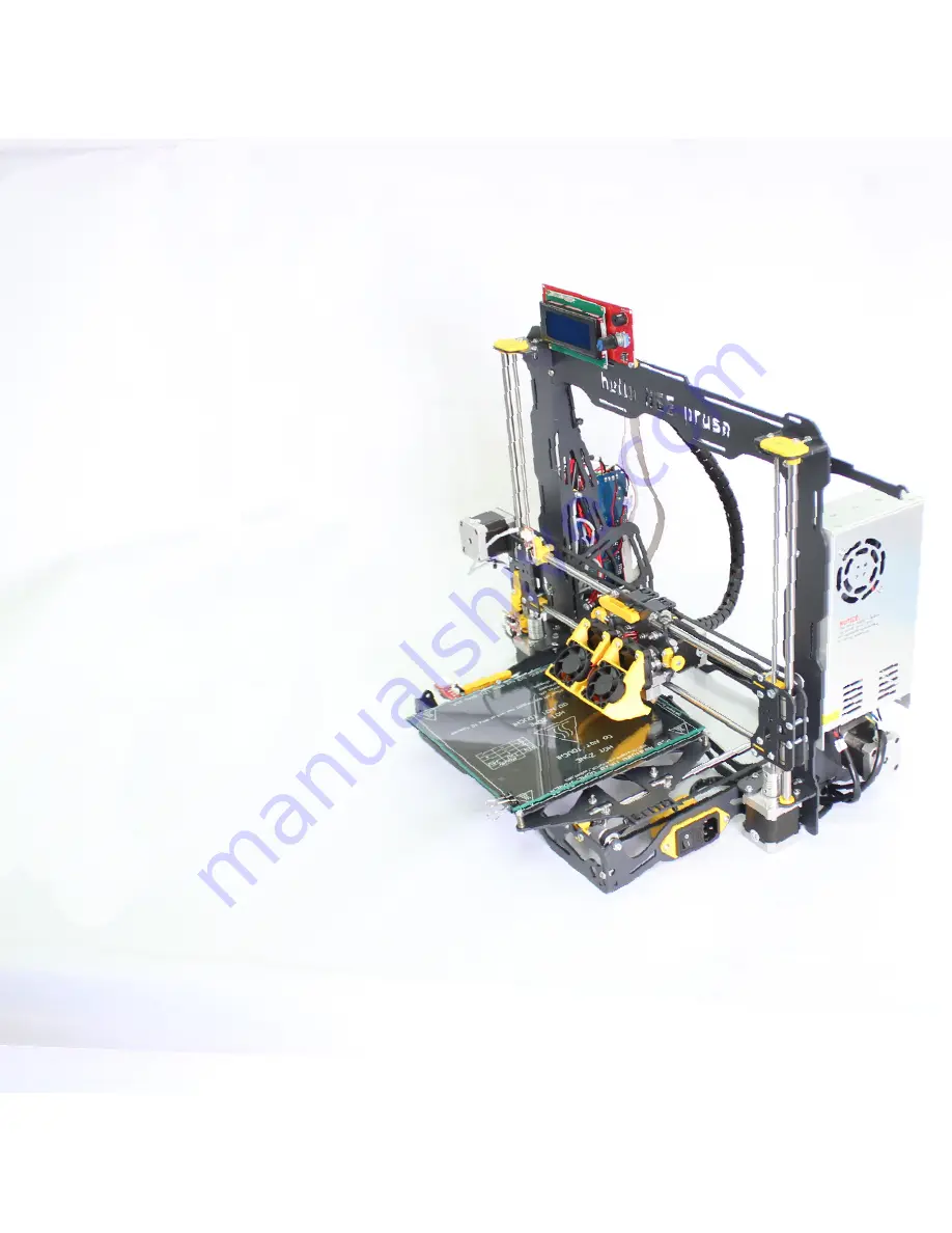
CONGRATULATIONS!
Your helloBEEprusa is now assembled, and it should
look like this. You may now connect your printer
to a power socket, with helloBEEprusa power cable,
and turn it on. You may use the USB cable provided
with the kit to communicate with the computer.
Please don’t forget to check the User Manual on our
Forum to learn how to setup your helloBEEprusa.
You can print any one of the printed parts
that are included in the kit yourself.
You can even print them in different materials
if you wish.
The STL files are available from our website,
and you can also download free add-ons to print
and improve your HelloBEEprusa.
You will find the sources here:
https://github.com/beeverycreative/helloBEEprusa-hardware
Hope you enjoy your helloBEEprusa!
Join us and share your experience here:
www.beeverycreative.com/forum.
HAPPY 3D PRINTING!
Содержание Hello BEE Prusa
Страница 1: ...ASSEMBLY MANUAL ...
Страница 2: ......
Страница 3: ...V3 310815 ...
Страница 10: ...A ASSEMBLING THE STRUCTURE ...
Страница 11: ...A 1 STRUCTURE ...
Страница 12: ...A 2 BUTTON HEAD SCREW DIN7380 M4X10 SERRATED LOCK WASHER DIN6798J M4 HEX THIN NUT 1 DIN439 M4 STRUCTURE ...
Страница 13: ...A 3 BUTTON HEAD SCREW DIN7380 M4X10 SERRATED LOCK WASHER DIN6798J M4 HEX THIN NUT 1 DIN439 M4 STRUCTURE ...
Страница 14: ...BUTTON HEAD SCREW DIN7380 M4X10 SERRATED LOCK WASHER DIN6798J M4 HEX THIN NUT 1 DIN439 M4 A 4 ...
Страница 15: ...A 5 BUTTON HEAD SCREW DIN7380 M4X10 SERRATED LOCK WASHER DIN6798J M4 HEX THIN NUT 1 DIN439 M4 STRUCTURE ...
Страница 16: ...A 6 BUTTON HEAD SCREW DIN7380 M4X10 SERRATED LOCK WASHER DIN6798J M4 HEX THIN NUT 1 DIN439 M4 STRUCTURE ...
Страница 17: ...BUTTON HEAD SCREW DIN7380 M4X10 SERRATED LOCK WASHER DIN6798J M4 HEX THIN NUT 1 DIN439 M4 A 7 ...
Страница 18: ...A 8 BUTTON HEAD SCREW DIN7380 M4X10 SERRATED LOCK WASHER DIN6798J M4 HEX THIN NUT 1 DIN439 M4 STRUCTURE ...
Страница 20: ...A 10 FLEX COUPLING 5MM You will need the hex key supplied with the kit to screw on the flex coupling ...
Страница 22: ...B ASSEMBLING THE BUILD PLATE STRUCTURE ...
Страница 24: ...B 2 8MM LINEAR BEARING SERRATED LOCK WASHER DIN6798J M4 HEX THIN NUT 1 DIN439 M4 U CLAMP A2 M4 20X20 5MM ...
Страница 26: ...B 4 END STOP LEVER X Y ...
Страница 28: ...B 6 BUTTON HEAD SCREW DIN7380 M4X10 SERRATED LOCK WASHER DIN6798J M4 HEX THIN NUT 1 DIN439 M4 ...
Страница 29: ...C ASSEMBLING THE EXTRUDER ...
Страница 30: ...C 1 STRUCTURE ...
Страница 32: ...C 3 CYL HEAD SCREW DIN912 M3X16 NYLOC NUT DIN985 M3 HEX HEAD SCREW DIN933 M5X10 U GROOVE WHEEL STRUCTURE ...
Страница 33: ...C 4 8MM LINEAR BEARING SERRATED LOCK WASHER DIN6798J M4 HEX THIN NUT 1 DIN439 M4 U CLAMP A2 M4 20X20 5MM ...
Страница 38: ...C 9 END STOP LEVER X Y ...
Страница 39: ...D ASSEMBLING THE X AXIS ...
Страница 40: ...D 1 X SUPPORT HEX THIN NUT 2 D439 M5 LINEAR GUIDE 8X385MM X STRUCTURE ...
Страница 43: ...D 4 X SUPPORT C EXTRUDER HEX THIN NUT 2 DIN439 M5 ...
Страница 44: ...D 5 STRUCTURE ...
Страница 47: ...D 8 CYL HEAD SCREW D912 M3X30 ADJUSTABLE Z END STOP ...
Страница 48: ...E HOW THE 3 AXES AND ALL THEIR COMPONENTS COME TOGETHER ...
Страница 50: ...E 2 LINEAR GUIDE 8X335MM Z Guides should slide freely ...
Страница 51: ...E 3 After this step move the extruder to feel if it slides freely on both axies X and Z ...
Страница 53: ...E 5 THREADED ROD DIN976 A2 M5X320 ...
Страница 55: ...E 7 GT2 RUBBER BELT CABLE TIE 2 5X100MM Place to put the Cable Tie ...
Страница 56: ...F ASSEMBLING THE ELECTRONICS ...
Страница 59: ...F 3 NYLOC NUT DIN985 M3 CYL HEAD SCREW DIN912 M3X16 DISPLAY SPACER CONTROL PANEL CONTROL PANEL CABLES ...
Страница 63: ...F 7 NYLOC NUT DIN985 M3 CYL HEAD SCREW DIN912 M3X16 ELECTRONICS COOLING FAN 24V WHITHOUT LABEL FAN SUPPORT ...
Страница 65: ...F 9 GLASS 3MM 214X200MM BINDER CLIPS 19MM ...


