Before you start to build your helloBEEprusa, check if you have the necessary tools to do it.
You will need the following:
NEEDED TOOLS
SET OF HEX KEYS
BOX CUTTER
CUTTER PLIERS
SPOOL HOLDER
REGULAR PLIERS
MARKER
FLATHEAD SCREWDRIVER
You will need a set of hex key for the assembly.
There is a 1.5mm hex key supplied with the kit.
You will need it towards the end.
Always a helpful tool.
You might need it to take out
the Structure Parts.
You will also need to remove some strands
from the printed parts with a cutter.
Take great care not to cut yourself
when doing this.
You need a marker to write on the
labels, for better guidance
while building helloBEEprusa.
Yes, there is a Spool Holder
included in the Structure frame,
which doubles as a spanner during assembly.
Sometimes you might need to use some
extra strengh assembling the printer.
Some of the structure’s metal components
might need some filing where the paint is thick,
or where there might be small fragments left over
from the manufacturing process.
SOFT FACE HAMMER
FILE
Содержание Hello BEE Prusa
Страница 1: ...ASSEMBLY MANUAL ...
Страница 2: ......
Страница 3: ...V3 310815 ...
Страница 10: ...A ASSEMBLING THE STRUCTURE ...
Страница 11: ...A 1 STRUCTURE ...
Страница 12: ...A 2 BUTTON HEAD SCREW DIN7380 M4X10 SERRATED LOCK WASHER DIN6798J M4 HEX THIN NUT 1 DIN439 M4 STRUCTURE ...
Страница 13: ...A 3 BUTTON HEAD SCREW DIN7380 M4X10 SERRATED LOCK WASHER DIN6798J M4 HEX THIN NUT 1 DIN439 M4 STRUCTURE ...
Страница 14: ...BUTTON HEAD SCREW DIN7380 M4X10 SERRATED LOCK WASHER DIN6798J M4 HEX THIN NUT 1 DIN439 M4 A 4 ...
Страница 15: ...A 5 BUTTON HEAD SCREW DIN7380 M4X10 SERRATED LOCK WASHER DIN6798J M4 HEX THIN NUT 1 DIN439 M4 STRUCTURE ...
Страница 16: ...A 6 BUTTON HEAD SCREW DIN7380 M4X10 SERRATED LOCK WASHER DIN6798J M4 HEX THIN NUT 1 DIN439 M4 STRUCTURE ...
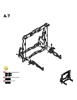
Страница 17: ...BUTTON HEAD SCREW DIN7380 M4X10 SERRATED LOCK WASHER DIN6798J M4 HEX THIN NUT 1 DIN439 M4 A 7 ...
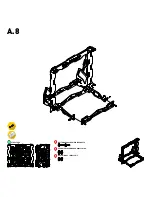
Страница 18: ...A 8 BUTTON HEAD SCREW DIN7380 M4X10 SERRATED LOCK WASHER DIN6798J M4 HEX THIN NUT 1 DIN439 M4 STRUCTURE ...
Страница 20: ...A 10 FLEX COUPLING 5MM You will need the hex key supplied with the kit to screw on the flex coupling ...
Страница 22: ...B ASSEMBLING THE BUILD PLATE STRUCTURE ...
Страница 24: ...B 2 8MM LINEAR BEARING SERRATED LOCK WASHER DIN6798J M4 HEX THIN NUT 1 DIN439 M4 U CLAMP A2 M4 20X20 5MM ...
Страница 26: ...B 4 END STOP LEVER X Y ...
Страница 28: ...B 6 BUTTON HEAD SCREW DIN7380 M4X10 SERRATED LOCK WASHER DIN6798J M4 HEX THIN NUT 1 DIN439 M4 ...
Страница 29: ...C ASSEMBLING THE EXTRUDER ...
Страница 30: ...C 1 STRUCTURE ...
Страница 32: ...C 3 CYL HEAD SCREW DIN912 M3X16 NYLOC NUT DIN985 M3 HEX HEAD SCREW DIN933 M5X10 U GROOVE WHEEL STRUCTURE ...
Страница 33: ...C 4 8MM LINEAR BEARING SERRATED LOCK WASHER DIN6798J M4 HEX THIN NUT 1 DIN439 M4 U CLAMP A2 M4 20X20 5MM ...
Страница 38: ...C 9 END STOP LEVER X Y ...
Страница 39: ...D ASSEMBLING THE X AXIS ...
Страница 40: ...D 1 X SUPPORT HEX THIN NUT 2 D439 M5 LINEAR GUIDE 8X385MM X STRUCTURE ...
Страница 43: ...D 4 X SUPPORT C EXTRUDER HEX THIN NUT 2 DIN439 M5 ...
Страница 44: ...D 5 STRUCTURE ...
Страница 47: ...D 8 CYL HEAD SCREW D912 M3X30 ADJUSTABLE Z END STOP ...
Страница 48: ...E HOW THE 3 AXES AND ALL THEIR COMPONENTS COME TOGETHER ...
Страница 50: ...E 2 LINEAR GUIDE 8X335MM Z Guides should slide freely ...
Страница 51: ...E 3 After this step move the extruder to feel if it slides freely on both axies X and Z ...
Страница 53: ...E 5 THREADED ROD DIN976 A2 M5X320 ...
Страница 55: ...E 7 GT2 RUBBER BELT CABLE TIE 2 5X100MM Place to put the Cable Tie ...
Страница 56: ...F ASSEMBLING THE ELECTRONICS ...
Страница 59: ...F 3 NYLOC NUT DIN985 M3 CYL HEAD SCREW DIN912 M3X16 DISPLAY SPACER CONTROL PANEL CONTROL PANEL CABLES ...
Страница 63: ...F 7 NYLOC NUT DIN985 M3 CYL HEAD SCREW DIN912 M3X16 ELECTRONICS COOLING FAN 24V WHITHOUT LABEL FAN SUPPORT ...
Страница 65: ...F 9 GLASS 3MM 214X200MM BINDER CLIPS 19MM ...


