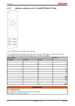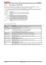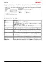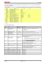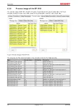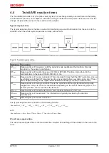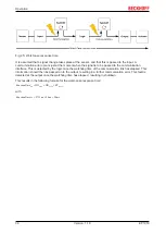
Operation
EP1918
22
Version: 1.1.0
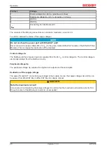
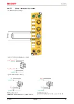
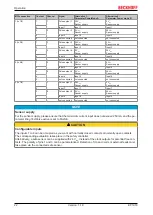
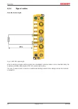
M12 connection
Contact
Channel
Signal
Alternative 1:
Parameter PowerMode A
Alternative 2:
Parameter Power mode B
1 (In 1/2)
1
1
Pulse output 1
24 V
DC
Sensor supply
0 V
DC
Sensor supply
2
Input 1
Input 1
Input 1
3
2
Pulse output 2
0 V
DC
Sensor supply
24 V
DC
Sensor supply
4
Input 2
Input 2
Input 2
5
-
not connected
not connected
not connected
2 (In 3/4)
1
3
Pulse output 3
24 V
DC
Sensor supply
0 V
DC
Sensor supply
2
Input 3
Input 3
Input 3
3
4
Pulse output 4
0 V
DC
Sensor supply
24 V
DC
Sensor supply
4
Input 4
Input 4
Input 4
5
-
not connected
not connected
not connected
3 (In 5/6)
1
5
Pulse output 5
24 V
DC
Sensor supply
0 V
DC
Sensor supply
2
Input 5
Input 5
Input 5
3
6
Pulse output 6
0 V
DC
Sensor supply
24 V
DC
Sensor supply
4
Input 6
Input 6
Input 6
5
-
not connected
not connected
not connected
4 (In 7/8)
1
7
Pulse output 7
24 V
DC
Sensor supply
0 V
DC
Sensor supply
2
Input 7
Input 7
Input 7
3
8
Pulse output 8
0 V
DC
Sensor supply
24 V
DC
Sensor supply
4
Input 8
Input 8
Input 8
5
-
not connected
not connected
not connected
NOTE
Sensor supply
For the sensor supply, please ensure that the maximum current input does not exceed 250 mA and the pa-
rameter
Diag TestPulse active
is set to FALSE.
CAUTION
Configurable inputs
The inputs 1 to 8 can be occupied as you want with normally closed contacts or normally open contacts.
The corresponding evaluation takes place in the safety controller.
Alternatively, a safe sensor can be supplied with 24 V
DC
, instead of the clock outputs for potential-free con-
tacts. The polarity of pins 1 and 3 can be parameterized. Detection of cross-circuits or external feeds must
take place via the connected safe sensor.
Содержание EP1918
Страница 2: ......
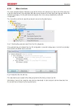
Страница 30: ...Operation EP1918 30 Version 1 1 0 Fig 19 Creating alias devices by the user ...
Страница 53: ...Appendix EP1918 53 Version 1 1 0 5 3 Certificates ...
Страница 55: ......

