Beckhoff EK1100 Скачать руководство пользователя страница 39

Mounting and wiring

EK110x, EK15xx

39

Version: 3.6

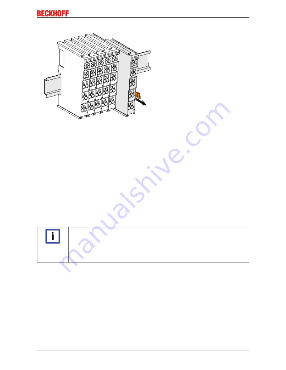
Disassembly

Fig. 23: Disassembling of terminal

Each terminal is secured by a lock on the mounting rail, which must be released for disassembly:

1. Pull the terminal by its orange-colored lugs approximately 1 cm away from the mounting rail. In doing

so for this terminal the mounting rail lock is released automatically and you can pull the terminal out of
the bus terminal block easily without excessive force.

2. Grasp the released terminal with thumb and index finger simultaneous at the upper and lower grooved

housing surfaces and pull the terminal out of the bus terminal block.

Connections within a bus terminal block

The electric connections between the Bus Coupler and the Bus Terminals are automatically realized by
joining the components:

• The six spring contacts of the K-Bus/E-Bus deal with the transfer of the data and the supply of the Bus

Terminal electronics.

• The power contacts deal with the supply for the field electronics and thus represent a supply rail within

the bus terminal block. The power contacts are supplied via terminals on the Bus Coupler (up to 24 V)
or for higher voltages via power feed terminals.

Note

Power Contacts

During the design of a bus terminal block, the pin assignment of the individual Bus Termi-
nals must be taken account of, since some types (e.g. analog Bus Terminals or digital 4-
channel Bus Terminals) do not or not fully loop through the power contacts. Power Feed
Terminals (KL91xx, KL92xx or EL91xx, EL92xx) interrupt the power contacts and thus rep-
resent the start of a new supply rail.

PE power contact

The power contact labeled PE can be used as a protective earth. For safety reasons this contact mates first
when plugging together, and can ground short-circuit currents of up to 125 A.

Содержание EK1100

Страница 1: ...Documentation EK110x EK15xx EtherCAT Bus Coupler 3 6 2017 10 05 Version Date...

Страница 2: ......

Страница 3: ...AT State Machine 33 3 4 CoE Interface notes 34 3 5 EKxxxx Optional Distributed Clocks support 34 4 Mounting and wiring 37 4 1 Instructions for ESD protection 37 4 2 Installation on mounting rails 37 4...

Страница 4: ...l rules for Class 1 laser 71 7 2 EtherCAT AL Status Codes 71 7 3 Firmware compatibility 71 7 4 Firmware Update EL ES EM EPxxxx 71 7 4 1 Device description ESI file XML 72 7 4 2 Firmware explanation 75...

Страница 5: ...1101 0080 18 EtherCAT Bus Coupler with ID switch Fast Hot Connect Connection M8 EK1100 0008 22 EtherCAT Bus Coupler Connection Fiber optic EK1501 25 EtherCAT Bus Coupler with ID switch Fiber Optic Mul...

Страница 6: ...ata diagrams and descriptions in this documentation Trademarks Beckhoff TwinCAT EtherCAT Safety over EtherCAT TwinSAFE XFC and XTS are registered trademarks of and licensed by Beckhoff Automation GmbH...

Страница 7: ...familiar with the applicable national standards Description of symbols In this documentation the following symbols are used with an accompanying safety instruction or note The safety instructions must...

Страница 8: ...th M8 sockets Chapter EtherCAT cabling wire bound moved from chapter Commissioning application notes to chapter Mounting and wiring 2 3 Update chapter Technical data Addenda chapter Installation instr...

Страница 9: ...ere is usually a description ESI EtherCAT Slave Information in the form of an XML file which is available for download from the Beckhoff web site From 2014 01 the revision is shown on the outside of t...

Страница 10: ...ion of I O PCB 0 no firmware necessary for this PCB hardware version of I O PCB 1 Unique serial number ID ID number In addition in some series each individual module has its own unique serial number S...

Страница 11: ...Fig 4 EL3202 0020 with batch numbers 26131006 and unique ID number 204418 Fig 5 EP1258 00001 IP67 EtherCAT Box with batch number 22090101 and unique serial number 158102 Fig 6 EP1908 0002 IP67 EtherC...

Страница 12: ...5xx 12 Version 3 6 Fig 7 EL2904 IP20 safety terminal with batch number date code 50110302 and unique serial number 00331701 Fig 8 ELM3604 0002 terminal with ID number QR code 100001051 and unique seri...

Страница 13: ...controller needed is the coupler to be connected via copper cable or optical fiber cable is the coupler to be addressed via IP or is it located in the unswitched network is the coupler to be controlle...

Страница 14: ...er Characteristic EK18xx EK9000 EKx000 EPxxxx CX8000 Protection class IP20 IP20 IP20 IP67 IP20 Higher level network technology 100 MBit FastEth ernet 100BASE TX 100 MBit FastEth ernet 100BASE TX diver...

Страница 15: ...wer RJ 45 socket may be used to connect further EtherCAT devices in the same strand The coupler supplies the connected terminals with the necessary E bus current for communication The coupler can supp...

Страница 16: ...5 V at higher current consumption the EL9410 power feed terminal can be used in addition max 2000 mA 25 C 55 C max 1000 mA 55 C Power contacts max 24 VDC max 10 A Electrical isolation 500 V power cont...

Страница 17: ...d if more current is required In the EtherCAT network the coupler can be installed anywhere in the Ethernet signal transfer section 100BASE TX The coupler thereby processes exclusively unaddressed MAC...

Страница 18: ...therCAT components are already quickly linked to the data communication after connection as standard Fast hot connect technology further reduces the connection time significantly enabling even faster...

Страница 19: ...cts max 24 VDC max 10 A Electrical isolation 500 V power contact supply voltage EtherCAT Dimensions W x H x D approx 44 mm x 100 mm x 68 mm Weight approx 105 g Permissible ambient temperature range du...

Страница 20: ...ports If corresponding ports are nevertheless connected a power reset of the devices involved branch terminal and coupler box is required With Fast Hot Connect devices the establishment of an Etherne...

Страница 21: ...the same way as Hot Connect groups specifying the associated group ID Fig 12 Configuration of a Fast Hot Connect group Corresponding Fast Hot Connect ports are marked red in the TwinCAT System Manage...

Страница 22: ...Fig 14 DC master setting This setting is automatically selected by the System Manager if there are no EtherCAT slaves in the configuration in which Distributed Clocks is activated DC in use should no...

Страница 23: ...rface is used to connect the coupler to the network the lower M8 socket serves for the optional connection of further EtherCAT devices in the same strand The coupler supplies the connected terminals w...

Страница 24: ...ion from UP Load Power supply E bus max 2000 mA 25 C 55 C Power contacts max 24 VDC max 10 A Electrical isolation 500 V power contact supply voltage EtherCAT Dimensions W x H x D approx 44 mm x 100 mm...

Страница 25: ...ith the necessary E bus current for communication The coupler can supply a maximum of 5V 2A Power feed terminals e g EL9410 must be integrated if more current is required In the EtherCAT network the c...

Страница 26: ...rCAT Device Protocol 100 MBaud HotConnect max number of configurable IDs 4096 Delay typical 1 s Bus connection 2 x SC Duplex Power supply 24 VDC 15 20 Current consumption 130 mA E bus current 4 E bus...

Страница 27: ...hnique using appropriate optical fiber cables An attenuation budget of 10 dBm is available between the EK1501 0010 and the associated EK1521 0010 branch The following factors can be taken as a basis f...

Страница 28: ...rent consumption 150 mA E bus current 4 E bus power supply 5 V depending on ambient temperature at higher current consumption the EL9410 power feed terminal can be used in addition max 2000 mA 25 C 55...

Страница 29: ...exadecimal ID switches for assigning an ID to a group of EtherCAT components The coupler supplies the connected terminals with the necessary E bus current for communication The coupler can supply a ma...

Страница 30: ...VDC 15 20 Input current 130 mA total E bus current 4 Current consumption 24 V DC typ 70 mA E Bus current consumption E bus power supply 5 V depending on ambient temperature at higher current consumpt...

Страница 31: ...ve Controller hardware processing unit of the EtherCAT protocol can have 1 to 4 ports which it controls itself Via an open port it can handle outgoing and incoming Ethernet traffic The following figur...

Страница 32: ...connected there and reports Link After the arrival of the data frame at Port 1 B from the terminal network this is passed on to Port 2 C and leaves the coupler at the following EtherCAT output if a sl...

Страница 33: ...ion Pre Operational Pre Op During the transition between Init and Pre Op the EtherCAT slave checks whether the mailbox was initialized correctly In Pre Op state mailbox communication is possible but n...

Страница 34: ...E Interface notes This device has no CoE Detailed information on the CoE interface can be found in the EtherCAT system documentation on the Beckhoff website 3 5 EKxxxx Optional Distributed Clocks supp...

Страница 35: ...vice XML revision in the configura tion Serial number of the component BK1150 from BK1150 0000 0016 from firmware 01 xxxx01yy CU1128 from CU1128 0000 0000 from firmware 00 xxxx00yy EK1100 from EK1100...

Страница 36: ...on procedure described here is only successful for the components de scribed above The checkboxes can be set for other components too although the hard ware does not support this function unless speci...

Страница 37: ...ntact with highly insulating materials synthetic fibers plastic film etc b Surroundings working place packaging and personnel should by grounded probably when handling with the devices c Each assembly...

Страница 38: ...lock clicks onto the mounting rail If the Terminals are clipped onto the mounting rail first and then pushed together without tongue and groove the connection will not be operational When correctly a...

Страница 39: ...ents The six spring contacts of the K Bus E Bus deal with the transfer of the data and the supply of the Bus Terminal electronics The power contacts deal with the supply for the field electronics and...

Страница 40: ...points for testing these Power Feed Terminals can be released and pulled at least 10 mm from the group of terminals WARNING Risk of electric shock The PE power contact must not be used for other poten...

Страница 41: ...anical fixture e g an earth terminal or reinforced end clamp The maximum total extension of the terminal segment without coupler is 64 terminals 12 mm mounting with or 32 terminals 24 mm mounting with...

Страница 42: ...position requires the mounting rail to be installed horizontally and the connection surfaces of the EL KL terminals to face forward see Fig Recommended distances for standard installation position Th...

Страница 43: ...w The Bus Terminal system offers different connection options for optimum adaptation to the respective application The terminals of ELxxxx and KLxxxx series with standard wiring include electronics an...

Страница 44: ...and eliminates the risk of wires being mixed up The familiar dimensions of the terminal only had to be changed slightly The new connector adds about 3 mm The maximum height of the terminal remains unc...

Страница 45: ...ation disassembly or wiring of the Bus Terminals Terminals for standard wiring ELxxxx KLxxxx and for pluggable wiring ESxxxx KSxxxx Fig 30 Connecting a cable on a terminal point Up to eight terminal p...

Страница 46: ...allows a maximum link length of 5 90 5 m if cables with appropriate properties are used See also the Design recommendations for the infrastructure for EtherCAT Ethernet Cables and connectors For conn...

Страница 47: ...ame ground potential must be used for the E Bus supply of all EtherCAT terminals in a terminal block 4 8 M8 Connector Cabling A list of the EtherCAT cable power cable sensor cable Ethernet EtherCAT co...

Страница 48: ...t cabling EtherCAT from the documentation Recommendations for the design of the infrastructure for EtherCAT Ethernet that is avail able for download at www Beckhoff com EtherCAT uses 4 wires for signa...

Страница 49: ...For usage of the EtherCAT connectors M8 of EK1100 0008 the following have to be noticed M8 connectors It is recommended to pull the M8 connectors tight with a nut torque of 0 4 Nm When using the torqu...

Страница 50: ...nal contacts allows the connection wires to be looped through to various terminal points The current load via the power contacts may not permanently exceed 10 A the supply line must therefore be prote...

Страница 51: ...supply fuse 1 depending on the required current consumption and hence the configured terminals typical max 1 A Power contacts fuse 2 permitted max 10 A slow blow The coupler electronics and the power...

Страница 52: ...are so called Passive Terminals The Passive Terminals have no current consumption out of the E Bus To ensure an optimal data transfer you must not directly string together more than 2 Passive Termina...

Страница 53: ...ing to UL508 with limited power consumption The current consumed by the device is limited to a max possible current consumption of 4 A Devices with this kind of certification are marked by this sign A...

Страница 54: ...protect against the rated operating voltage being exceeded by more than 40 due to short term interference voltages The individual terminals may only be unplugged or removed from the Bus Terminal sys t...

Страница 55: ...of the Beckhoff terminal systems in potentially explo sive areas ATEX Pay also attention to the continuative documentation Notes about operation of the Beckhoff terminal systems in potentially explosi...

Страница 56: ...lus a protective colored jacket The core and the cladding have a different index of refraction causing the light waves modes a mode is a natural wave in the optical fiber to be reflected back into the...

Страница 57: ...recommended for connecting to the EK1501 EK1501 0010 The advantage of the PC physical contact version of this connector is the crowned end face which allows the region of the fiber core that is relev...

Страница 58: ...ptical fiber cable always pull the connector to release the locking mech anism never pull the optical fiber cable itself Note Crossover cables Not that crossover cables may have to be used for connect...

Страница 59: ...lymer fiber is 1 mm thick and consists of a 0 98 mm thick core made of polymethyl methacrylate PMMA as well as a thin sheath In order to enable the guidance of light using the effect of total reflecti...

Страница 60: ...ion For each additional plug connector the maximum permitted distances typically reduces by 6 5 m 5 2 2 2 Application with EK1541 Note Recommended plug connectors and POF cables For the connection of...

Страница 61: ...x is the lower outlet in the connection sockets Figure Transmitter channels in the EK1541 Be sure to observe the safety instructions 71 for class 1 lasers Attention Use of blind plugs In order to avoi...

Страница 62: ...nnector set consisting of a plastic sanding gauge sheets of abrasive paper with grain size 600 and pink polishing sheets Once assembled the connector can be used right away Materials required 1 POF ca...

Страница 63: ...ude no more than 1 5 mm from the front openings Close the connector by folding the upper and lower halves together until they engage Fig 44 Cable inserted in the connector Fig 45 Closed connector When...

Страница 64: ...rpendicular as possible In order to achieve a uniform result use the abrasive paper in the form of a figure of 8 until the fibers are flush with the sanding gauge Then clean the sanding gauge and the...

Страница 65: ...Commissioning application notes EK110x EK15xx 65 Version 3 6 Fig 49 Fine polished fibers in the connector...

Страница 66: ...n state flashing Pre Operational The Bus Coupler is in pre operational state single flash Safe Operational The Bus Coupler is in safe operational state on Operational The Bus Coupler is in operational...

Страница 67: ...he Bus Coupler is in pre operational state single flash Safe Operational The Bus Coupler is in safe operational state on Operational The Bus Coupler is in operational state flickers Bootstrap Firmware...

Страница 68: ...l The Bus Coupler is in pre operational state single flash Safe Operational The Bus Coupler is in safe operational state on Operational The Bus Coupler is in operational state flickers Bootstrap Firmw...

Страница 69: ...tional The Bus Coupler is in pre operational state single flash Safe Operational The Bus Coupler is in safe operational state on Operational The Bus Coupler is in operational state flickers Bootstrap...

Страница 70: ...The Bus Coupler is in pre operational state single flash Safe Operational The Bus Coupler is in safe operational state on Operational The Bus Coupler is in operational state flickers Bootstrap Firmwar...

Страница 71: ...110x and EK15xx Couplers have no firmware 7 4 Firmware Update EL ES EM EPxxxx This section describes the device update for Beckhoff EtherCAT slaves from the EL ES EM EK and EP series A firmware update...

Страница 72: ...not be retrofitted it is a component of many new developments from year of manufacture 2016 Following the update its success should be verified ESI Revision e g by means of an online scan in TwinCAT C...

Страница 73: ...EtherCAT system documentation Note Update of XML ESI description The device revision is closely linked to the firmware and hardware used Incompatible com binations lead to malfunctions or even final s...

Страница 74: ...s configured In this case the configuration can be adapted with the Copy Before button The Extended Information checkbox must be set in order to display the revision Changing the ESI slave identifier...

Страница 75: ...Note The change only takes effect after a restart Most EtherCAT devices read a modified ESI description immediately or after startup from the INIT Some communication settings such as distributed cloc...

Страница 76: ...ve sup ports this This CoE directory can only be displayed if a slave is connected and operational offline The EtherCAT Slave Information ESI XML may contain the default content of the CoE This CoE di...

Страница 77: ...2 Firmware Update Proceed as follows unless instructed otherwise by Beckhoff support Valid for TwinCAT 2 and 3 as EtherCAT master Switch TwinCAT system to ConfigMode FreeRun with cycle time 1 ms defau...

Страница 78: ...via an rbf file Controller firmware for processing I O signals FPGA firmware for EtherCAT communication only for terminals with FPGA The firmware version number included in the terminal serial number...

Страница 79: ...yed right click the table header and select Properties in the context menu Fig 64 Context menu Properties The Advanced Settings dialog appears where the columns to be displayed can be selected Under D...

Страница 80: ...he terminal must have FPGA firmware version 10 or higher Older firmware versions can only be updated by the manufacturer Updating an EtherCAT device The following sequence order have to be met if no o...

Страница 81: ...Manager select the terminal for which the FPGA firmware is to be updated in the example Terminal 5 EL5001 and click the Advanced Settings button in the EtherCAT tab The Advanced Settings dialog appea...

Страница 82: ...age to the device A download of firmware to an EtherCAT device must not be interrupted in any case If you interrupt this process by switching off power supply or disconnecting the Ethernet link the Et...

Страница 83: ...mponents there Beckhoff Headquarters Beckhoff Automation GmbH Co KG Huelshorstweg 20 33415 Verl Germany Phone 49 0 5246 963 0 Fax 49 0 5246 963 198 e mail info beckhoff com Beckhoff Support Support of...

Страница 84: ...em Manager 21 Fig 14 DC master setting 22 Fig 15 Example EK1100 EK1100 0008 EtherCAT coupler with 3 ports 31 Fig 16 Internal and external port assignment for Bus Coupler EK1100 and EK1100 0008 32 Fig...

Страница 85: ...xxxx 67 Fig 52 Diagnostic LEDs for Bus Coupler EK1501 68 Fig 53 Diagnostic LEDs for Bus Coupler EK1501 0010 69 Fig 54 Diagnostic LEDs Bus Coupler EK1541 70 Fig 55 Device identifier consisting of name...

Отзывы: