background image


DV 16800.03    Issue  1   12/11 

Page  2-I 


GK615-X 


Table of contents


Section 

INSTALLATION 

Page


2.1


General remarks


2-1


2.2


Pre-installation check


2-1


2.2.1


Visual inspection


2-1


2.2.2


Mechanical installation in an vehicle


2-1


2.3


Installation wiring


2-1


2.3.1


General


2-1


2.3.2


Modification of antenna connection for installation in a vehicle


2-2


2.3.3


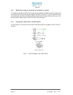
Connecting an external PTT or foot PTT switch


2-2


Fig. 2-1 

Fig. 2-2 

Fig. 2-3


Interwiring diagram 5 way DIN socket J4 

Interwiring diagram DC socket P3 

Interwiring diagram Connector P2


2-2 

2-2 

2-3


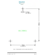
Fig. 2-4 

Fig. 2-5 

Fig. 2-6


Dimensions of portable VHF Station GK615-X 

Drilling template for vehicle mounting bracket 

GK615-X Vehicle mounting bracket GK615-X


2-4 

2-5 

2-6


Содержание GK615-X

Страница 1: ...15 X Installation and Operation Manual DV 16800 03 Issue 2 January 2013 Becker Flugfunkwerk GmbH Baden Airpark Geb ude B 108 77836 Rheinm nster Telefon 07229 305 0 E Mail info becker avionics de or su...

Страница 2: ...3 LIST OF EFFECTIVE PAGES Page No Date Page No Date Title 1 I 1 II 1 1 1 4 1 5 1 6 2 I 2 II 2 1 2 6 3 I 3 II 3 1 3 12 12 11 12 11 12 11 01 13 12 11 12 11 12 11 12 11 12 11 DV 16800 03 Article Number 0...

Страница 3: ...escription Page 1 1 Introduction 1 1 1 2 Purpose of equipment 1 1 1 3 General description 1 1 1 4 Variants survey 1 2 1 5 Technical data 1 3 1 6 Scope of delivery 1 4 1 7 Accessories not included 1 6...

Страница 4: ...tery for a time of 8 10 hours should be charged Charging can be made via the included battery charger or if the GK 615 is in a car installed via the Car Battery Cable 1KA615 not included in the car Al...

Страница 5: ...dification and Changes N A 8 Circuit Diagrams N A 1 2 Purpose of equipment Carrying case and transceiver together form a portable VHF station The easily portable VHF station can be used for example fo...

Страница 6: ...is switched on LOW BATT is indicated Appearance about every 5 seconds if the supply voltage of the transceiver is below the threshold defined in the installation setup The transceiver is still operab...

Страница 7: ...Dyn mike 2 mV 10 mV Headphone 40 mW 300 Ohms Antenna impedance 50 Ohms Battery number 1 Battery type dry lead acid battery Capacity 2 Ah 12 V nominal Weight 4 4 kg Dimensions H 270 mm W 175 mm D 80 mm...

Страница 8: ...cope of delivery Battery 12 V 2 Ah Article No 0883 158 391 Microphone 1PM 415 Article No 0603 120 951 Speaker with Microphone 1PH012 only by GK615 1 Article No 0498 475 951 Handle Article No 0549 967...

Страница 9: ...01 13 Page 1 5 GK615 X Power supply Article No 0530 158 918 AC connector cable Article No 0295 728 276 Carrying bag Article No 0893 854 959 Antenna 1A 415 Article No 0884 294 952 VHF transceiver Arti...

Страница 10: ...d VHF antennas Steel band antenna 1A415 1 Article No 0586 137 375 Multiplex antenna 1A415 2 Article No 0586 129 375 Mike holder for 1PM415 Peiker HV5 Article No 0505 897 268 Car Battery Cable GK615 1K...

Страница 11: ...General 2 1 2 3 2 Modification of antenna connection for installation in a vehicle 2 2 2 3 3 Connecting an external PTT or foot PTT switch 2 2 Fig 2 1 Fig 2 2 Fig 2 3 Interwiring diagram 5 way DIN so...

Страница 12: ...Page 2 II DV 16800 03 Issue 1 12 11 GK615 X Blank...

Страница 13: ...amaged pushbuttons knobs or dials 2 2 2 Mechanical installation in a vehicle Attachment is by means of the unit mounting bracket This is to e secured to a suitable point using three bolts When choosin...

Страница 14: ...to mount the antenna connection on the rear To do this remove both half shells and remove the bolts attaching the antenna socket to the front panel Remove the cover on the back and fit the antennae s...

Страница 15: ...DV 16800 03 Issue 1 12 11 Page 2 3 GK615 X Fig 2 2 Interwiring diagram Connector P2 Fig 2 3 Location Fuse and Connector P2 on bottom...

Страница 16: ...Page 2 4 DV 16800 03 lssue 1 12 11 GK615 X Fig 2 4 Dimensions of portable VHF Station GK615 X...

Страница 17: ...DV 16800 03 lssue 1 12 11 Page 2 5 GK615 X Fig 2 5 Drilling template for vehicle mounting bracket GK615 X...

Страница 18: ...Page 2 6 DV 16800 03 lssue 1 12 11 GK615 X Fig 2 6 Car mounting bracket and handle GK615 X...

Страница 19: ...1 1 Receive Operation 3 5 3 2 1 2 Transmit Operation 3 5 3 2 2 Operation Modes 3 6 3 2 2 1 Standard Mode 3 6 3 2 2 2 Direct Tune Mode 3 6 3 2 2 3 Channel Mode 3 7 3 2 2 4 Scan Mode 3 8 3 2 2 5 Squelch...

Страница 20: ...Page 3 II DV 16800 03 Issue 1 12 11 GK615 X Blank...

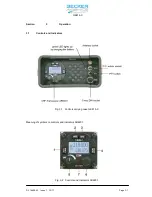
Страница 21: ...16800 03 Issue 1 12 11 Page 3 1 Section 3 Operation 3 1 Controls and Indicators Fig 3 1 Controls carrying case GK 615 X Meaning of symbols on controls and indicators AR6201 Fig 3 2 Controls and Indica...

Страница 22: ...tes storage procedure 4 SCN Exchange SCAN Short press during standard mode or scan mode exchanges preset frequency and active frequency Long press activates scan mode 5 Volume Knob Switches the transc...

Страница 23: ...ive or preset from which the audio is derived STO The transceiver performs a storage operation 3 1 3 Start Up Connect the antenna and the mike speaker to the corresponding connection jacks a Switch ON...

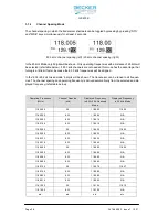
Страница 24: ...l be shown The transceiver can be tuned to all frequen cies The channel spacing and operating frequency is derived automatically from the selected and dis played frequency refer table below Operating...

Страница 25: ...enus storing external intercom 3 2 1 2 Transmit Operation If PTT is pressed the transceiver switches into transmit operation Microphone s signals are modula ting the transmitter Transmit operation is...

Страница 26: ...o frequencies at the same time SCAN Mode can be entered and left by long press of SCN key 3 2 2 1 Standard Mode Standard mode can be entered by consecutive short pressing of MDE Standard mode will be...

Страница 27: ...de the active frequency is indicated in the top line In the bottom line of the display the channel number is indicated When changed from direct tune mode to channel mode the active frequency stays the...

Страница 28: ...f display is shown in picture below Blinking In addition to the blinking of the preset frequency an audio notification BEEP can be enabled in the installation setup If enabled a short BEEP will be hea...

Страница 29: ...imilar to the channel mode But as difference STO is displayed on left side of the display On the top line active frequency is indicated On the bottom line channel number is indicated If channel is fre...

Страница 30: ...ies can be recalled in channel mode 3 2 2 9 Pilots Menu The pilots menu can be entered by long press of MDE key The pilots menu can be left by waiting 5 seconds doing no action or by short press of MD...

Страница 31: ...ding on supply voltage trans ceiver may have a reduced performance Below 10 V speaker output is switched off Possible reasons for indication Problems with capacity of accumulator gliders Power interru...

Страница 32: ...on A speech test is to be performed before startup and it should be noted that if the speech test is carried out close to the ground station the results may be positive even if the antenna cable is br...

Отзывы: