background image

75

Advanced Utilities

All the subsequent chapters:

Measuring the Environment Temperature with the ENV

Sensor

 on page 75,

Display Mode Settings 

on page 76,

Transmitter/Switch Simulation 

on page 79,

Data Logging

 on page 82,

Generating Signals Using External Devices

 on page 85 and

Printing

 on page 89

describe the use of additional features that are available in MC5P.
Some of the utilities are firmware options and/or they require some
additional hardware before they can be utilized.

Measuring the Environment Temperature with the ENV Sensor

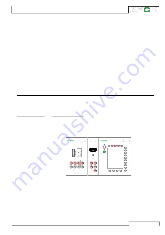
The ENV-sensor is a optional environment temperature probe that can be connected to
the ENV sensor interface on the left side of MC5P. 

Required settings

Options/description

Quantity

ENV-Temp.

Funct/Port

T-ENV(mea)

 (selected automatically when the

corresponding 

Quantity

 setting is activated )

Note!

The ENV-sensor is not accurate enough to be used as a refer-
ence sensor. Use it as a tool for obtaining the environment tem-
perature during calibration or as a temperature measurement tool
when the accuracy of the measurement is not critical.

ELECTRICAL MODULE

FOR MC5P

S/N

M U L T I F U N C T I O N         C A L I B R A T O R

MC5P

E

?

ET

ELECTRICAL AND TEMPERATURE MODULE 

FOR MC5P

S/N

Max 60 VDC/30 VAC

Max 60 VDC

Max 30 VAC 

OUTPUT

SENSOR  MEASURE & SIMULATE

INTERNAL REFERENCE JUNCTION 

FOR THERMOCOUPLES 

T/C, Low V

4-w meas

R, RTD

V, 

I

,

3 & 4-w meas

Open

Close

Open

Close

T/C INT. RJ 

T/C 

WIRES 
ONLY

(ENV), ENVIRONMENTAL 

TEMPERATURE SENSOR 

(EXT), EXTERNAL 

PRESSURE MODULE 

MEASURE

+24V

I

meas/sink

HART

®

2-w xmtr

V,   ,

Low V

Com

Advanced Utilities

Содержание MC5P

Страница 1: ... The above not withstanding we can assume no responsibility for any errors in this manual or their eventual consequences We reserve rights to make modifications to this manual without any further notice For more detailed technical data about the MC5 Multifunction Calibrator please contact the manufacturer Copyright 2003 2006 BEAMEX OY AB Ristisuonraitti 10 FIN 68600 Pietarsaari FINLAND Tel 358 10 ...

Страница 2: ... trademark owned by Oy Beamex Ab HART is a registered trademark of the HART Communication Foundation Any use of the word HART hereafter in this document implies the registered trademark Other trademarks are property of their respective owners ...

Страница 3: ...the Internal Reference Junction Module 27 Introduction 2 About This Manual 2 Typographical Conventions 3 Unpacking and Inspection 3 MC5P Hardware 4 Operational Sections and Connections 4 Base Unit and the Display 5 Electrical Module E module 5 Electrical and Temperature Module ET module 6 Reference Junction Module 6 Internal Pressure Modules 7 External Pressure Modules 7 Environment Temperature In...

Страница 4: ...al Measurements 49 Mathematical Special Measurements 50 Minimum value 50 Maximum value 50 Min Max value 50 Rate of Change 50 Special Filtering and Resolution 51 Deviation Measurement 51 Special Measurements Using Two Ports Simultaneously 52 Difference Measurement 52 Redundant Measurement 53 Generating Simulating 54 General 54 Changing the Value of the Generated Simulated Signal 55 Current Generati...

Страница 5: ...ices 85 Controlling the External Device in Basic Mode 86 Pressure Controller Settings 87 Temperature Controller Settings 88 Printing 89 Part C Advanced Operation and Configurations Additional Information 90 Things to Consider when Measuring Pressure 91 General 91 Pressure Type 91 Pressure Modules and their Naming Conventions 92 Square Rooting 92 Thermocouple Measurement Simulation Connections and ...

Страница 6: ...ors 116 Temperature Indicators and Recorders 118 Electrical Limit Switches 120 Using External Devices in Calibration Mode 122 MC5P s Support for Instrument Adjustment 123 Maintaining MC5P s Instrument Database 124 Adding New Instruments 124 Editing Instrument Data 125 General Data Page 125 Instrument Input Page 126 Instrument Output Page 127 Calibration Settings Page 127 Calibration Instructions P...

Страница 7: ...em The best way to fill the form is to answer the items as it applies and send the form to us when all items are answered There are however no definite restricitions fill in the form when you feel like it all items need not be answered Then send it to Beamex using one of the possibilities listed below Mail Beamex Oy Ab Quality Feedback Ristisuonraitti 10 FIN 68600 Pietarsaari FINLAND Fax 358 10 55...

Страница 8: ...______ _________________________________________________________________ 9 Did anything in the product disappoint you In that case please specify _________________________________________________________________ _________________________________________________________________ 10 Any ideas You want to propose to Beamex so that we can improve our products operations and or services ________________...

Страница 9: ...n to what MC5P is and what the parts of this User Guide concentrate on A general description of MC5P s hardware A general description of MC5P s firmware The modularity and options of MC5P Safety precautions and warnings Briefly about how to service MC5P ...

Страница 10: ... temperature process instruments It is capable of communicating with external devices such as pressure controllers MC5P also com municates with HART field instruments MC5P represents the state of the art in accuracy adaptability and all round usability About This Manual This User Guide is divided in four parts A B C and D Part A discusses general matters There is also a chapter about safety Part B...

Страница 11: ...ere are signs of obvious mechanical damage package contents are incomplete or the instrument does not operate according to specifications con tact the purchasing sales office as soon as possible The standard accessories are as follows Calibration Certificate This User Guide Warranty Card Computer communication cable If any internal pressure modules are present A pressure hose set Two test leads an...

Страница 12: ...nal Sections and Connections All sections and connections are presented in detail on the next pages Note Keep in mind that the previous picture as well as all pictures of MC5P in this manual has an example configuration of modules The configuration of your MC5P may vary significantly from the one in the picture Open Close Close T C WIRES ONLY XXXXXXX XXXXXXX 24V V Internal Pressure Modules Electri...

Страница 13: ... module is joined with the Base Unit The E module can measure the fol lowing quantities voltage current and frequency It can also be used when counting pulses or detecting the state of a switch Addition ally there is a possi bility to generate current and supply an instrument with a 24 VDC power supply The E module also includes the HART modem needed when utiliz ing the HART communication option T...

Страница 14: ...T C plugs and stripped wires Open the fixing screw on the left side of MC5P before connecting the wires plug to the Reference Junction Module Make sure to connect the wires plug as the po larity is indicated on the Reference Junc tion Module Remember to tighten the fastening screw when the wires plug are connected Hand tightening is adequate Do not pull out the wires plug without first opening the...

Страница 15: ...ft If the use of tools is required to secure the con nection typically pressure modules with a pressure range higher than 20 bar apply the counterforce by placing a 14 mm approx 9 16 A F spanner on the flats found in the module s connector The overpressure protection of the internal pressure modules vents to the inside of the module rack Remember to be cautious when working with pressure and press...

Страница 16: ... for printouts of user interface screens e g calibrations results Warning Use only cables provided by Beamex when connecting MC5P to a PC or a printer Auxiliary Instrument Interface The location of the Auxiliary Instrument connector also varies de pending on the configuration of the MCS100 calibration station which MC5P is part of The connector is however marked with the text AUX The AUX connector...

Страница 17: ...entering of values The Keys Above the Display The Light key toggles the back light of the display on and off It is also used when setting the contrast and the brightness of the dis play see chapter Base Unit on page 5 and when printing screenshots see chapter Printing on page 13 The Help key displays case sensitive help The On Off key switches MC5P on and off Press the On Off key for about half a ...

Страница 18: ...ion When entering num bers the 9 key produces the number 9 To finish entering a number you will have to use the key or use the D OK Function Key when available Memory MC5P has a dynamic memory allocation system This means that there is not a specific area of memory reserved for e g instrument data All free memory may be used for anything that requires more memory Thus there is no exact limit for t...

Страница 19: ...r Stepping and Ramping Configuring the Calibrator Setting Time and Date Instrument Database Maintenance Instrument Adjustment Viewing the Results Instrument Calibration Transmitter Simulation Data Logging Measurement Generation Simulation BASIC MODE CALIBRATION MODE STARTUP PROCEDURE MAINTE NANCE MENU STRUCTURE The following chapters briefly describe each main function Startup Procedure Every time...

Страница 20: ...attention was directed on this matter when creating the calibra tor MC5P may be used as a stand alone calibrator i e all instru ment data and calibration history data is saved in MC5P s own memory Optionally MC5P also communicates with calibration soft ware MC5P supports the use of instruction texts They help the techni cian to perform the calibration as fluently as possible You may en ter three k...

Страница 21: ...l information on printing is found in part C of this manual Warning Only use the printer that is available as an option Using any other printers may damage the printer or MC5P or even both of them 10 11 2003 15 02 1 Voltage ET Low V Low V Sensor Meas Basic Mode is the focal point of the calibrator s menu structure Advanced functions are in D Menu and C Others To measure generate or simulate select...

Страница 22: ...glass when MC5P is working on something that takes time A question mark when an error occurred A symbol indicating communication with an external device e g a HART instrument or a controller or Note that the fourth section is empty for most of the time The sym bols are visible only when needed Close Window 1 Window 2 MENU Mode Others Setup Setup 0 4521 mbar gauge Alarm P1 INT2C 1 000000 2 bar POC4...

Страница 23: ...e and keys to scroll the pop up list To select an option in the pop up list use either the key or the key To close the pop up menu without se lecting anything press the key or the D Close Function Key 3 Another menu with new options replaces the previous menu Sometimes the Function Keys can also open another menu In the previous picture the Window 1 setup menu is opened In this case Function Key B...

Страница 24: ... second corresponding data related to the output signal The third window displays the er ror graph The error graph is also seen among calibration result data Configuration Window There are plenty of configuration windows in MC5P The picture be side is the configuration window for Ramping settings The common thing for all configu ration windows is that they reserve the whole display area for the co...

Страница 25: ... ways to start editing a numeric field 1 Press a numeric key or key Then the entered value replaces the old value 2 Press the key or the C Edit Function Key available in some configuration windows Then you can edit the old value New digits appear at the end of the old value Accept the new value by pressing the key To discard the edited 10 11 2003 15 05 Back Page Next MENU 12 02 2000 10 29 As Found...

Страница 26: ...nu with the available characters opens for selecting Use the numeric keys 1 to 7 to select the character Use the cur sor keys to move the cursor in the text field Select the character with the or the key Use the C çDelete Function Key to remove unwanted characters If the character you want to use is not seen in the list of available characters try the or the key to see more alternatives Accept the...

Страница 27: ...a Pop up List can be done with an additional way com pared Drop Down Lists Each time you push the numeric menu key that opened the Pop up List the cursor advances one step Selection Lists Selection lists are used when you have to choose one of several op tions Selection lists are often large thus almost reserving the whole window Selection lists can be longer than the visible part When the cursor ...

Страница 28: ...board battery pack common electronics and the ENV AUX and COMP PRT connectors as well as a connector for an external pressure module PX1 Voltage low voltage current and frequency measurement Also pulse counting switch testing HART communication 1 current generation and 24 V loop supply Internal Pressure Modules 2 PM s Modules with positive and compound gauge pressure measurement capability and a b...

Страница 29: ...onal information on the battery operated portable printer pres sure controllers and temperature baths dry blocks is available in part C of this manual Firmware options The standard firmware shipped with MC5P is capable of performing all normal measurement generation simulation and calibration tasks The optional tools give you additional features that enhance MC5P s functionality The following firm...

Страница 30: ...ssure of a pressure module exceeds the module s maximum pressure value the overpressure protector vents excess pressure iside the MCS100 rack Certifications and Compliances EC Declaration of Conformity MC5P Conforms to the EMC directive 89 336 EEC and the Low Voltage Directive 72 23 EEC as attested by conformity with the fol lowing harmonized standards Product Standard EN 61326 Safety Requirements...

Страница 31: ...of MC5P is evidently damaged When MC5P is not functioning as expected After prolonged storage in unfavorable conditions After serious damage during transport Sometimes it is necessary to use a portable radio transceiver while working with the calibrator To prevent calibration errors caused by the radio frequency interference keep the radio far at least 1 meter from the calibrator and the circuit u...

Страница 32: ...70 F Applying higher pressure can be haz ardous To avoid damaging the module use hand tightening only when connecting the pressure measurement hoses max torque 5 Nm approx 3 6 lbf ft If the use of tools is required to secure the connection typically pressure modules with a pressure range higher than 20 bar apply the counterforce by placing a 14 mm approx 9 16 A F spanner on the flats found in the ...

Страница 33: ... sure that the other people in the same space are aware of the danger Use of liquid pressure medium is recommended with pressure measurement modules at higher pressure range Use water or suitable hydraulic oil Check that the used liquid is not aggres sive against the materials used in the transducer or tubing When using liquid minimize the amount of air in the system So you can minimize the amount...

Страница 34: ...ads page and see what it says about MC5P firmware versions and downloads All you need is a Personal Computer and the Computer communi cation cable that connects MC5P to one of the serial ports in your PC Remember to backup all the instrument data in MC5P using e g a calibration management software Also check for possible release notes accompanying the updated file Recalibrating MC5P Only laborator...

Страница 35: ...acts of the Internal Reference Junction Module The contacts of the Internal Reference Junction Block may need cleaning from time to time The time period varies depending on the environment MC5P is used in Carefully open the cover of the Internal Reference Junction Block by using a screwdriver as a wrench Now you can see the contacts Remove all impurities and press back the cover The cover is se cu...

Страница 36: ...28 General Empty ...

Страница 37: ...and Basic Operation Things discussed in Part B What happens during the startup procedure Measuring signals and doing some special measurements Generating simulating signals Step and Ramp functions Alarm limits ...

Страница 38: ... press the D Continue function key If a module s version number cannot be seen the module is not included in the MC5P at hand The calibration due date that is listed in the startup window is the earliest calibration due date for all connected modules If the cali brator requires recalibration MC5P stops at the calibrator informa tion window and the text Calibrate Soon appears below the cali bration...

Страница 39: ...rations you always return to the Basic Mode In Basic Mode the two available measurement generation simulation windows have default settings based either on factory settings or settings defined when MC5P was previously used The first time the D Menu key is pressed the Window 1 Setup menu is available Other possible menus can be selected from the function keys B Window 2 Setup and C Others The latte...

Страница 40: ...ment min max value etc Perform a Limit Switch Test Set alarm limits Use the ramping function Use the stepping function Available options depend on the installed modules Next Measuring on page 37 Generating Simulating on page 54 Special Measurements on page 49 Alarm Limit Settings on page 69 Special Generations on page 65 10 11 2003 15 04 1 Pressure 2 Current P2 INT20C 1 0000 20 6840 bar g E Curren...

Страница 41: ...Function Port setting in the window menu If the picture has more than two terminals circled then the lighter part is somehow optional In the following picture the HART terminal is optional during current measure ment ELECTRICAL MODULE FOR MC5P S N M U L T I F U N C T I O N C A L I B R A T O R MC5P E ET ELECTRICAL AND TEMPERATURE MODULE FOR MC5P S N Max 60 VDC 30 VAC Max 60 VDC Max 30 VAC OUTPUT SE...

Страница 42: ...34 Startup and Basic Operation Warning Do not apply voltage higher than 50 V max 2 A between any terminals ...

Страница 43: ...o measure the required pressure type Port P1 INTxxxx P2 INTyyyy if applicable up to P9 INTzzzz Using External Modules Select the external pressure module port with a connected pressure module and a suitable measuring range and with an abil ity to measure the required pressure type e g Port PX1 EXTxxxx Connecting and Removing External Pressure Modules An external pressure module may be connected an...

Страница 44: ...sure Module If a secondary pressure module is ac tive in the selected window a pop up menu will appear for choosing either to zero the primary or the secondary pressure module NOTE We recommend that you zero the used pressure module every time before you start measuring pressure with it When using an external pressure module zero it every time you change its position Next Special Measurements on p...

Страница 45: ...asurement parallel to a test diode can be found in part C chapter Current Measurement Parallel to a Test Diode Connections on page 99 Next Current Generation on page 56 Special Measurements on page 49 Alarm Limit Settings on page 69 Calibration see Part D ELECTRICAL MODULE FOR MC5P S N M U L T I F U N C T I O N C A L I B R A T O R MC5P E ET ELECTRICAL AND TEMPERATURE MODULE FOR MC5P S N Max 60 VDC...

Страница 46: ...elect either Function port ET LowV mea or E LowV mea and choose a suitable unit The following pictures display the ac tive terminals for both available ports ET LowV mea 500 mV E LowV mea 1 V ELECTRICAL MODULE FOR MC5P S N M U L T I F U N C T I O N C A L I B R A T O R MC5P E ET ELECTRICAL AND TEMPERATURE MODULE FOR MC5P S N Max 60 VDC 30 VAC Max 60 VDC Max 30 VAC OUTPUT SENSOR MEASURE SIMULATE INT...

Страница 47: ...s on page 49 Alarm Limit Settings on page 69 Calibration see Part D ELECTRICAL MODULE FOR MC5P S N M U L T I F U N C T I O N C A L I B R A T O R MC5P E ET ELECTRICAL AND TEMPERATURE MODULE FOR MC5P S N Max 60 VDC 30 VAC Max 60 VDC Max 30 VAC OUTPUT SENSOR MEASURE SIMULATE INTERNAL REFERENCE JUNCTION FOR THERMOCOUPLES T C Low V 4 w meas R RTD V I 3 4 w meas Open Close Open Close T C INT RJ T C WIRE...

Страница 48: ...ndow This means that the circuit is broken or the connection is wrong Wrong connec tion may also cause erroneous reading typically too low If neces sary use the 2 wire ohm measurement to check the wiring before final connection Next RTD and Resistance Simulation on page 62 RTD Measurement Temperature on page 46 Special Measurements on page 49 Alarm Limit Settings on page 69 Calibration see Part D ...

Страница 49: ...volt age within the range 10 V to 30 V MC5P shows voltages above approx 1 5 V as open contact and voltages below approx 1 5 V as closed contact Hint Switch state detection may also be used for binary signal detection Next Limit Switch Test on page 42 Calibration see Part D ELECTRICAL MODULE FOR MC5P S N M U L T I F U N C T I O N C A L I B R A T O R MC5P E ET ELECTRICAL AND TEMPERATURE MODULE FOR M...

Страница 50: ...in Part D of this manual In Basic Mode MC5P does not support limit switch testing when simulating resistance or an RTD sensor The limit switch test in Calibration Mode also supports resistance and RTD sensor input Performing the Limit Switch Test Configure e g Window 1 to either mea sure or generate simulate the switch s in put signal Function keys D Menu and A Window 1 Setup in Basic Mode and Win...

Страница 51: ...o find more information when measuring a switch s input signal Pressure Measurement on page 35 Using External Modules on page 35 Voltage Measurement on page 38 Current Measurement on page 37 Thermocouple Measurement Temperature on page 47 RTD Measurement Temperature on page 46 Where to find more information when generating a switch s input signal Voltage Generation on page 58 Current Generation on...

Страница 52: ...h State Sensing on page 41 Pulse Counting on page 45 Frequency Generation on page 60 Calibration see Part D ELECTRICAL MODULE FOR MC5P S N M U L T I F U N C T I O N C A L I B R A T O R MC5P E ET ELECTRICAL AND TEMPERATURE MODULE FOR MC5P S N Max 60 VDC 30 VAC Max 60 VDC Max 30 VAC OUTPUT SENSOR MEASURE SIMULATE INTERNAL REFERENCE JUNCTION FOR THERMOCOUPLES T C Low V 4 w meas R RTD V I 3 4 w meas O...

Страница 53: ...ext Frequency Measurement on page 44 Switch State Sensing on page 41 Pulse Generation on page 61 Calibration see Part D ELECTRICAL MODULE FOR MC5P S N M U L T I F U N C T I O N C A L I B R A T O R MC5P E ET ELECTRICAL AND TEMPERATURE MODULE FOR MC5P S N Max 60 VDC 30 VAC Max 60 VDC Max 30 VAC OUTPUT SENSOR MEASURE SIMULATE INTERNAL REFERENCE JUNCTION FOR THERMOCOUPLES T C Low V 4 w meas R RTD V I ...

Страница 54: ...This means that the circuit is broken or the connection is wrong Wrong connection may also cause erroneous reading typically too low If necessary use the 2 wire ohm measurement to check the wiring before final connection Next RTD and Resistance Simulation on page 62 Thermocouple Measurement Temperature on page 47 Resistance Measurement on page 40 Special Measurements on page 49 Alarm Limit Setting...

Страница 55: ...nal information is found in chapter Internal Reference Junction on page 93 Additional information is found in chapter External Reference Junction on page 94 ELECTRICAL MODULE FOR MC5P S N M U L T I F U N C T I O N C A L I B R A T O R MC5P E ET ELECTRICAL AND TEMPERATURE MODULE FOR MC5P S N Max 60 VDC 30 VAC Max 60 VDC Max 30 VAC OUTPUT SENSOR MEASURE SIMULATE INTERNAL REFERENCE JUNCTION FOR THERMO...

Страница 56: ...to the ET module s R RTD con nectors there is no galvanic isolation between the thermo couple and the RTD sensor Next Thermocouple Simulation on page 63 RTD Measurement Temperature on page 46 Voltage Measurement on page 38 Special Measurements on page 49 Alarm Limit Settings on page 69 Calibration see Part D Problems with thermovoltage measurement See Error situations on page 96 ...

Страница 57: ...the type of spe cial measurement from the provided pop up list or deactivate a special measurement by selecting the option None Some of the special measurements do not require any additional information They start immediately after they are activated Rate of Change Measurement Special Filtering and Resolution Redundant Measurement and Deviation Measurement do how ever need some additional informat...

Страница 58: ...nts Maximum Reading Min Max value Start the minimum maximum value measurement by selecting D Menu and B Window 2 Setup if needed or 1 Special Measurements Min Max Readings Rate of Change Start the rate of change measure ment by selecting D Menu and B Window 2 Setup if needed or 1 Special Measurements Rate of Change Before the special measurement is started MC5P prompts for the rate of change unit ...

Страница 59: ...ted from the read ing of the main port Start the de viation measurement by selecting D Menu and B Window 2 Setup if needed or 1 Special Measurements Deviation Meas You can enter the reference value when you start the special mea surement mode Note Keep in mind that when the displayed deviation reading is small compared to the actual reading a significant part of the deviation value may be measurem...

Страница 60: ...ent by selecting D Menu and B Window 2 Setup if needed or 1 Special Measurement Difference Meas Notes Difference measurement is not available as an option in the list of special measurements unless two measurement ports are activated in the same window No setting window appears but the calculated difference is dis played in the special measurement row The measurement value of the second port may b...

Страница 61: ... two measurement ports are selected for use in the same window The mea surement value of the second port is displayed on the special mea surement row You may assign the allowed deviation value to be dis played on the Extra info row at the bottom of the window When setting the allowed difference take the accuracies of the measurements into account If the measuring spans of the selected ports are di...

Страница 62: ...he modules that include terminals required for the generation simulation Most generated simulated signals are done with the ET module but current generation may also be done with the E module Because of MC5P s modularity you may or may not have the required module If the module is not included in your MC5P the 1 Quantity and 2 Function Port settings needed for the generation simulation are not ava...

Страница 63: ...r the key or the D OK Function Key Note The dual function of the keys and is not available in a generation field The keys only represent numbers Fine Tuning the Generated Simulated Signal Press either of the left or right arrow keys or to start the Fine Tun ing of the selected numeric field Then one of the digits in the num ber in underlined indicating which digit can be fine tuned If needed press...

Страница 64: ... there is no gal vanic isolation between the measuring circuit and the current gen eration The voltage between the output connectors of the ET module is limited to 15 Volts There is no sinking possibility in the ET mod ule Using the E module s output termi nals When generating current from the E module s output terminals you can either use MC5P s internal 24V supply source mode or use an external ...

Страница 65: ... Make sure that you don t exceed the maximum current allowed by the instrument under test If you open the mA generation loop MC5P tries to maintain the current by increasing the output voltage If you then close the loop again the current is first too high but returns quickly to the correct level If this current peak could damage the compo nents of the loop make sure that the loop will not open or ...

Страница 66: ...current is 5 mA MC5P displays both the set value and the internally measured value for the generated voltage in the selected window ELECTRICAL MODULE FOR MC5P S N M U L T I F U N C T I O N C A L I B R A T O R MC5P E ET ELECTRICAL AND TEMPERATURE MODULE FOR MC5P S N Max 60 VDC 30 VAC Max 60 VDC Max 30 VAC OUTPUT SENSOR MEASURE SIMULATE INTERNAL REFERENCE JUNCTION FOR THERMOCOUPLES T C Low V 4 w mea...

Страница 67: ...millivolts manu ally Warning If you short circuit the voltage output MC5P tries to maintain the voltage by increasing the output current If you then re move the short circuit the voltage is first too high but returns quickly to the correct level If this voltage peak could damage the components of the circuit make sure that the circuit can not be shorted or protect the circuit against overvoltage F...

Страница 68: ... set to symmetric or all positive The amplitude Vpp setting range is 0 01 V to 12 V Next Pulse Generation on page 61 Frequency Measurement on page 44 Special Generations on page 65 Calibration see Part D ELECTRICAL MODULE FOR MC5P S N M U L T I F U N C T I O N C A L I B R A T O R MC5P E ET ELECTRICAL AND TEMPERATURE MODULE FOR MC5P S N Max 60 VDC 30 VAC Max 60 VDC Max 30 VAC OUTPUT SENSOR MEASURE ...

Страница 69: ...f you change the frequency after the pulse generation has started the frequency is adjusted during the current cycle but the frequency is not correct until the next cycle Next Frequency Generation on page 60 Pulse Counting on page 45 Special Generations on page 65 ELECTRICAL MODULE FOR MC5P S N M U L T I F U N C T I O N C A L I B R A T O R MC5P E ET ELECTRICAL AND TEMPERATURE MODULE FOR MC5P S N M...

Страница 70: ...s Notes In RTD and resistance simulation MC5P monitors the resistance measurement cur rent If the current is too high it cannot simulate the right resistance value In that case it shows the message H CURR Respectively if the measurement current is so low that it may affect the accuracy the message L CURR is displayed Accurate operation of the simulation elec tronics requires that the current suppl...

Страница 71: ...se an External Reference Junction select Function Port ET TCx sim and choose one of the available Reference Junction compensation methods Entered 0 C or available RTD sensors Additional information is found in chapter Internal Reference Junction on page 93 Additional information is found in chapter External Reference Junction on page 94 ELECTRICAL MODULE FOR MC5P S N M U L T I F U N C T I O N C A ...

Страница 72: ... of a wire wound device Short circuit the measuring device for the time of resistance measurement The resistance measure ment may damage the device if you do not install the short circuit For more information on resistance measurement see chapter Resistance Measurement on page 40 Warning If you short circuit the thermocouple simulation output MC5P tries to maintain the voltage by increasing the ou...

Страница 73: ...he Step or Ramp Configuration Window Open the window setup menu for the generation simulation quan tity that you want to configure a Stepping function for The menu commands are D Menu and B Window 2 Setup if needed Press the numeric key to open the second menu page Choose 3 Step Ramp and Either 1 Step or 2 Ramp in the next menu 12 04 2002 12 52 ET Voltage Generation E Switch Sense V Open 2 Switch ...

Страница 74: ...s field This indicates that the size of the step that reaches the 100 range limit is smaller than the defined step size See the rightmost example To stop stepping press the function key C Stop Stepping This applies for both a continuous stepping Repeats field set to zero and a stepping with a predetermined amount of repeats max value 65535 The Stepping configuration windows shown below are opened ...

Страница 75: ... display the result of the settings zero and a ramping with a predetermined amount of repeats max value 65535 To stop ramping press the function key C Stop Ramping This applies for both a continuous ramping Repeats field set to RAMPING 10 11 2003 16 10 Quantity Port Rise Time Wait in 100 Fall Time Repeats 0 continuous Range Current ET I gen 1 1 2 2 8 0000 16 0000 s mA 0 100 2 Wait in 0 s s s Stop ...

Страница 76: ... are as small as possible slower ramps use smaller steps Warning Do not configure the range settings so that they exceed the allowed input range of the connected instrument MC5P deter mines the limits of the range settings based on the selected quantity and port not the connected instrument ...

Страница 77: ...se MENU Mode Others Window 1 Window 2 Setup Setup Sensor Supply None mbar gauge Alarm 0 5 bar Special Measurement None Function and Port Info Alarm Second Extra Info Port Info Close MENU Mode Others Window 1 Window 2 Setup Setup P2 EXT100 Second port Close MENU Mode Others 0 70834 mbar gauge Alarm P1 INT2C 1 000000 2 bar 0 5 0 4374 2 Current bar Pressure E Current Measurement Quantity Pressure P1 ...

Страница 78: ... setup menu as follows Symbol Definition No limit settings Low limit is set High limit is set Low and high limits are set Low and high limits are set Low High Low rate limit is set High rate limit is set Low and high rate limits are set Low and high rate limits are set Low High All limits are set Acknowledging alarms When an alarm limit is exceeded MC5P emits an audible alarm The alarm can be ackn...

Страница 79: ...discussed in Part C How to configure MC5P to suit your requirements Advanced Utilities available in Basic Mode Additional information Useful during pressure measurement thermocouple measurement simulation and resistance RTD measurement simulation ...

Страница 80: ...tmost picture is the settings page that opens first You can scroll between the pages using the B Next Page Function Key Note All changes in settings become valid immediately 11 11 2003 8 33 SETTINGS Date Format Time Format Language Auto off Delays 0 never min Calibrator Backlight Sound Volumes Key Click Alarm Attention Outside Span Error h mm 24h English 0 5 Low High Medium Medium Low Close dd mm ...

Страница 81: ...larm Medium Attention Medium Outside Span Medium Error Medium All settings have three different possible values Low Medium High The ones starting with an asterisk may also be set to Off Line Frequency Select the setting that suits the local line frequency 50 or 60 Hz Note that wrong line frequency setting af fects the accuracy of MC5P The default setting is 50 Hz Display Backlight Power Select the...

Страница 82: ...s The date must always be given in dd mm yyyy format no matter what the configured date format is The time must always be given in the 24 hour format no matter what the configured time format is The date and time will be updated when you press the D Accept Function Key 11 11 2003 8 35 TIME DATE SETTINGS Date dd mm yyyy Time hh mm ss 16 13 02 06 22 2002 Cancel Accept Edit ...

Страница 83: ...Required settings Options description Quantity ENV Temp Funct Port T ENV mea selected automatically when the corresponding Quantity setting is activated Note The ENV sensor is not accurate enough to be used as a refer ence sensor Use it as a tool for obtaining the environment tem perature during calibration or as a temperature measurement tool when the accuracy of the measurement is not critical E...

Страница 84: ...ineering Units Display Mode if the quantity or port of the window s assigned to the special Display Mode are changed Warning Be careful not to mistakenly read a value shown in special Dis play Mode as a value shown in Engineering Units MC5P al ways displays the true measurement in the window s lower most row Extra Info row when a special Display Mode is ac tive 11 11 2003 8 35 P2 INT20C 1 0 20 7 b...

Страница 85: ...ther measurement before scaling was started the other mea surement is automatically stopped Note Remember to set the amount of decimals to be displayed for a Cus tom Unit The default value is 3 SCALING 11 11 2003 8 36 Quantity Port Pressure P1 INT2C Measured Range kPa Stop Ramping Field Start Cancel Edit 0 100 kPa 0 000 100 000 Scaled Mode Scaled Unit mA Scaled Range 0 100 4 000 20 000 Transfer Fu...

Страница 86: ...ch Error Display Mode is invoked is considered as the instrument s output signal and the other window as the input sig nal Start the Error Display Mode as described in chapter Display Mode Settings on page 76 Enter the Measured Range for both the in put and the output signal the Error Calculation Method and the Transfer Function input output correlation The true output value is displayed in the Ex...

Страница 87: ... you want to simulate a transmitter or a switch Note To be able to start the Transmitter Switch Simulation both Ba sic Mode windows need to be configured accordingly If e g window 2 is not assigned for generating simulating a signal MC5P can not start transmitter simulation 11 11 2003 8 41 P2 INT20C 100 2068 kPa g E Current Source Sink gauge kPa 0 02 mA 2 Current 1 Pressure End MENU Measurement mA...

Страница 88: ...imulation is active The second row of both windows display the active port and the input output range of the simulated transmit ter Notes To Zero a pressure module during Transmitter Simulation Press D MENU and 7 Zero Pressure Module When pausing the Transmitter Simulation you can change the gen eration simulation signal as in Basic Mode Warning Remember to scale the output signal of the Transmitt...

Страница 89: ...eactuating points The sec ond row of the lower window displays the actuated and deactuated output of the switch Note To Zero a pressure module during Switch Simulation Press D MENU and 7 Zero Pressure Module Warning Remember to scale the output signal of the Switch Simulation so that the instrument connected to the output signal loop is not damaged SWITCH SIMULATION 11 11 2003 8 45 Stop Ramping Fi...

Страница 90: ...gging configuration window is reserved for seven measurement channels and the lower part for general settings The following subchapters describe how they are configured Assigning Measurement Ports to Channels Move the cursor to one of the meas urement channel rows in the Data Logging configuration window Press C Edit to open the following channel settings window Select the measurement port first T...

Страница 91: ...ximum values of Samples and Time settings also depend on the available free memory If you enter values that require more memory than is avail able MC5P automatically replaces the entered value with the currently allowed maximum value When a data log is done you can enter a name for the results Starting the Data Log To start logging select B Data Log ging in the Data Logging configu ration window S...

Страница 92: ...ckly jump to a column To see the minimum maximum and average values of the log see the next result page by selecting B Next Page Removing Datalog results To remove a set of data logging results select D MENU 3 Re move Datalog Data To remove all datalog results select D MENU 4 Remove All Datalog Data Transferring the Results to a Personal Computer A 32 bit Windows software called MC5_Datalog exe is...

Страница 93: ... avail able when the selected Quantity is Pressure To be able to communicate with the external device MC5P requires some additional data which you can enter in the window that opens automatically after you have selected the Controller Settings menu option This is presented on the next page mbar gauge Alarm 0 5 bar Controller Settings Close MENU Mode Others Window 1 Window 2 Setup Setup Sensor Supp...

Страница 94: ...layed in the window it was assigned to e g POC4 in the adja cent picture Enter target values setpoints for the connected exter nal device in the numerical field following the device name Note If a field indicator cannot be moved to the external device s setpoint field or the field indicator is not seen at all make sure the connections and the settings are in order When MC5P is able to communicate ...

Страница 95: ... the generated pres sure it is not passed on to MC5P in MC5P s Basic Mode Therefore you should always connect the generated pressure also to a pres sure measurement module in MC5P When a controller is used in Calibration Mode Input Mode Con trol is used when the instrument s input signal is measured with MC5P and Input Mode Ctrl Mea when the controller communi cates the generated pressure to MC5P ...

Страница 96: ...ing on the device configuration The Device Address field is not visible for temperature controllers that do not need the setting Serial communication settings The communication settings shown in the window are the ones required by MC5P The settings vary depending on the con nected temperature controller usually the default communication settings of the tem perature controller If the settings have ...

Страница 97: ...nd the computer uses the same interface the COMP PRT connector Notes If you press the and keys and no printer is connected the serial port is unavailable for PC communication for about a minute The printer is configured for communication with MC5P when deliv ered If you inadvertently alter the configuration please contact Beamex for instructions on how to restore the settings Warning Only use the ...

Страница 98: ...antity and port in MC5P The Sensor type and the Reference Junction Mode has to be set accordingly too Wrong settings give erroneous results Whenever this additional information may be of use in a measure ment generation or simulation text describing the function refers to one of the following chapters An experienced user need not jump to read this supplemental text but for a beginner we highly rec...

Страница 99: ...e pressure may be zero negative or positive Most of MC5P s pressure modules actually mea sure gauge pressure although they may be used for measur ing other pressure types too Differential pressure measurement requires a special dif ferential pressure module that has an input available for both the reference pressure and the given pressure To be able to measure absolute pressure with MC5P s gauge p...

Страница 100: ...00mC 400 mbar 6 INT2C 1 2 bar 14 5 30 Notes Compound modules with a max nominal pressure above 1 bar e g INT2C are able to measure negative pressures down to 1 bar Compound modules with a max nominal pressure below 1 bar e g INT400mC are only able to measure as deep negative pressures as positive pressures The name of the internal barometric pressure module is B Eternal pressure modules have a nam...

Страница 101: ...i mea or ET TCi sim MC5P automatically selects the Internal Refer ence Junction compensation method No other Reference Junction compensation methods are available unless the measur ing simulating port is changed Connection when measuring simulating thermovoltage using Internal Reference Junction Mode Note The range of the Internal Reference Junction s temperature com pensation is 10 50 C 14 122 F ...

Страница 102: ...xed to a temperature that differs from 0 C The Reference Junction temperature is controlled and the controller s set point is not 0 C Note this method is of use only if the accuracy of the controller is better than MC5P s own Reference Junction Module A compensation box is used and the Reference Junction temperature setting is other than 0 C There is no Reference Junction compen sation in the meas...

Страница 103: ...emperature and Reference Junction compensation method Entered also RJ mode 0 C S N Max 60 VDC 30 VAC OUTPUT SENSOR MEASURE SIMULATE T C Low V 4 w meas R RTD V I 3 4 w meas Tref Copper T C sensor or a T C signal receiver Temperature Controller T C materials T C Low V S N Max 60 VDC 30 VAC OUTPUT SENSOR MEASURE SIMULATE T C Low V 4 w meas R RTD V I 3 4 w meas T C Low V Copper T C materials Tref T C ...

Страница 104: ...ond with the used thermocouple The selected Reference Junction mode is not in accordance with the used wiring Extension or compensation cable type or connections are incorrect The polarity of the cables are incorrect MC5P or the instrument under test displays random readings during thermocouple measurement Incorrect connections The wiring is broken Interference from a mobile phone or a radio trans...

Страница 105: ...rough the resistor from the two left side terminals MC5P mea sures the voltage drop across the entire current loop and across the low side con nection wire If both left side connection wires are identical MC5P can compensate for the resistance of the connection wires 4 wire System MC5P sources current through the resistor from the two left side terminals MC5P mea sures the voltage drop across the ...

Страница 106: ...ical MC5P can compensate for the resistance of the con nection wires When the compensation loop wiring sys tem is used MC5P displays the text 3 wire 2 wire System Calibrator sources current through the resistor and measures the voltage drop across the same terminals The result is acceptable if the resistance of the connection wires is low S N Max 60 VDC 30 VAC OUTPUT SENSOR MEASURE SIMULATE T C Lo...

Страница 107: ...the externally supplied output current of the transmitter For more infor mation concerning test diode connections of HART instruments see Appendix 1 chapter Connecting MC5P and a HART Instru ment on page 138 Note In higher temperatures The leakage of the diode in the instrument may affect the accuracy S N MEASURE 24V Imeas sink HART 2 w xmtr V Low V Com Max 60 VDC Max 30 VAC I Input signal X S N M...

Страница 108: ...als The ET module is also capable of doing the following double tasks Measuring Low Voltages or thermocouples connected to any terminal used when measuring thermocouples and at the same time either measuring or simulating an RTD with the RTD sen sor terminals Generating Low voltages or simulating a thermocouple con nected to any terminal used when simulating thermocouples and at the same time meas...

Страница 109: ...calibration is and the phases of a typical calibration proce dure A description of a calibration procedure using MC5P Some application examples on how to perform the calibration of certain instruments Creating editing and deleting Instruments Viewing calibration results ...

Страница 110: ...bration the instrument data is downloaded from a calibration software The calibration is done just as in stand alone calibration but calibration procedures are downloaded from a software and the saved results are uploaded to the calibration software Off line calibration requires the QCAL option It also requires the computer communication cable to connect MC5P to a PC s serial port Note MC5P also i...

Страница 111: ...ibration The guide texts may be entered in MC5P or they may be down loaded from a PC with a calibration software Start As Found test Save As Found results No of repeats done Read Starting Guide Text no yes Adjustment required Within limits As Left test Adjustment If it is not possible to adjust the maximum error below the Reject if limit consider replacing the instrument with a more accurate one R...

Страница 112: ...r limit settings Reject if acceptance limit for found maximum error Adjust if the instrument need to be adjusted if this limit is exceeded Do not adjust if adjusting the instrument is not necessary of use and Adjust to after adjusting the maximum error should not exceed this limit MC5P has a special adjustment utility tool that can be used when the input signal of the instrument is generated simul...

Страница 113: ...As Left calibrations The pictures above display different As Left calibration graphs after two different kinds of adjustments In the leftmost picture the error is minimized at the end points of the instrument range This results in a relatively notable error in the middle of the span If the middle of the span is the area where the measurement is usually situated then this method is not recom mended...

Страница 114: ...red E Low Voltage E Measured E ET measured ET ET Measured ET Generated ET Keyed none Keyed none HART E Current Measured E Current Measured E E generated E Keyed none ET generated ET HART E Keyed none Resistance Measured ET Resistance Measured ET Keyed none Simulated ET HART E Keyed none Pressure Measured INT or EXT Pressure Measured INT or EXT Keyed none Controlled INT or EXT HART E Controlled Mea...

Страница 115: ... where both the input signal and the output signal is connected to the ET module INPUT QUANTITY INPUT METHOD OUTPUT QUANTITY OUTPUT METHOD Voltage Generated Low Voltage ET Measured Generated TC Temperature Measured Generated RTD Temperature Measured Low Voltage ET Measured RTD Temperature Measured ET Generated RTD Temperature Measured Current ET Generated Low Voltage ET Measured ET Generated TC Te...

Страница 116: ...ce ID of an already calibrated instrument is tick marked When you move the cursor the inverted text the additional data presented in the lower part of the screen changes to reflect the data of the current instrument Select one of the available instruments by pressing the or the C Select key Note If there are a lot instrument data in MC5P s memory displaying the list may take a few seconds 11 11 20...

Страница 117: ...e device and start the communication To calibrate the selected instrument simply press C Calibrate General calibration procedures are discussed in chapter A Cali bration Procedure Using MC5P on page 110 Some calibration examples are available starting from chapter Examples of Instru ment Calibration on page 113 If a Starting Guide text is written it appears before the Calibration Windows are opene...

Страница 118: ...c Mode 2 Start the calibration run by pressing B Start The way MC5P passes through all calibration points depends on the Cali bration Method setting In Automatic calibration MC5P generates simulates or communicates with an external device capable of generat ing simulating the input signal See chapters About Automatic Calibration on page 112 and About Manual Calibration on page 112 Note You can pau...

Страница 119: ...er case you will see the possible Finishing Guide text before you are back viewing the Instrument Data Note If you are calibrating instruments using off line method then please keep in mind this When you upload the results from MC5P to the calibration software the results are by default also left in MC5P s memory To free memory in MC5P by deleting the results see De leting Instruments on page 128 ...

Страница 120: ...ith the next calibration point If the input signal never stabilizes the symbol is visible con tinuously but you want MC5P to save the results anyhow press the B Force Accept Function Key About Manual Calibration In manual calibration you will have to manually set the input signal to a level that the next calibration point requires Manual calibration is possible in almost all situations Even for ca...

Страница 121: ...n the Maximum Allowed Calibration Point Deviation limit an hourglass is shown in the input measurement window s lower right corner When autocapture snatches the input and output signal values MC5P emits a beep and the next target value for the input is dis played Examples of Instrument Calibration This User Guide has only a few examples of how to calibrate an instrument Many calibration procedures...

Страница 122: ...gured MC5P to provide the supply volt age or current connect the ET module s output terminals marked with a circle in the picture to the sensor s supply terminals For more information on sensor supply configuration see chapter Instrument Input Page on page 126 2 Connect the pressure source both to the instrument s input and to the pre se lected pressure module INT EXT XPM If a pressure output cont...

Страница 123: ...roller is available and the Calibration Mode is set to Automatic Additional Calibration Method specific data is in chapters About Automatic Calibration and About Manual Calibration both on page 112 5 Save or reject the results as is de scribed in chapter A Calibration Pro cedure Using MC5P on page 110 6 Either do another calibration run or re turn to the Instrument window Hint These instructions c...

Страница 124: ...rature Preparations 1 Connect the calibration bath dry block to MC5P s AUX connector if applicable using the communication cable pro vided with MC5P Place the sensor of the instrument and the sensor of the reference thermometer into the calibra tion bath dry block Connect it them to suitable terminals in MC5P RTD or T C If the sensor is a thermocouple select one of the available reference junction...

Страница 125: ...n proceeds au tomatically More information on Cali bration Methods is in chapter About Automatic Calibration and About Manual Calibration both on page 112 5 Save or reject the results as is de scribed in chapter A Calibration Pro cedure Using MC5P on page 110 6 Either do another calibration run or re turn to the Instrument window Hint With small changes this procedure should also suit all tempera ...

Страница 126: ...ethods The internal Reference Junction module is in use The reference junction is fixed to 0 C The reference junction tempera ture is entered The reference junction tempera ture is measured externally using an RTD connected to the RTD ter minals See Part C for additional information concerning the reference junction meth ods 3 If the sensor to be simulated is an RTD the used wiring system depends ...

Страница 127: ...d displaying the de fault value and enter the actual reading This method is useful when calibrating indicators with digital display or when the input signal cannot be fine adjusted 3 Accept the points using the B Accept Readings Function Key 4 Save or reject the results as is de scribed in chapter A Calibration Pro cedure Using MC5P on page 110 5 Either do another calibration run or re turn to the...

Страница 128: ...tion Mode and select the instrument to be calibrated 2 Start the calibration as is presented in chapter A Calibration Procedure Us ing MC5P on page 110 MC5P does the Prescan if it is enabled During the prescan MC5P searches for approxi mate values for the actuating and deactuating point This speeds up the final test without sacrificing accuracy The prescan test is done only once in a calibration B...

Страница 129: ... that each pair of actuation deactuation points have to be accepted manually If the prescan stops and displays an error message try widening the scan range It is also advisable to have the scan range sym metrical in relation to the actuation deactuation points Hint This procedure also suits other types of switches How to calibrate other types of switches may be adapted by combining the informa tio...

Страница 130: ...ler Settings to select the Controller type and activate the communication Notes The Input Method option Con trolled is available for the follow ing Input Quantities Pressure RTD temperature and TC tem perature The Input Method option Con trolled Meas is available for the following Input Quantities Pres sure Temperature RTD Temperature and TC Temperature More information on how to create instrument...

Страница 131: ...dows open the adjustment utility by pressing the C Adjust Function Key Press the Function Keys B C and D to quickly change the value of the in put signal Additionally the input signal field is editable during instrument ad justment This makes it possible for you to enter generation simula tion values other than the ones available via the Function Keys Hint For help on how to adjust trim HART instr...

Страница 132: ...is kept in the memory Normally you can safely store some hundreds of instruments and their calibration results without having out of memory messages If you want to delete instruments or calibration data from MC5P s memory see chapters Deleting Instruments on page 128 and Deleting Calibration Results on page 130 Adding New Instruments If you go to Calibration Mode but there are no instruments in MC...

Страница 133: ...his with the Copy Instrument option available in menu Editing Instrument Data The instrument data pages may be re edited whenever you want Note Only the following fields may be edited if the instrument data is downloaded from a calibration software valid for Beamex s calibra tion software QD3 and QM6 Input Span and Output Span General Data Page Out of the four text fields in the up per part of thi...

Страница 134: ...ty includes the corresponding common fields as the input quantity The same additional fields are also available for the output quantity with the following exceptions addi tions If the output quantity is Pressure the pressure type is always Gauge Output quantity Frequency in cludes a Trigger Level setting Remember to also check the Transfer Function setting at the bottom of the display The default ...

Страница 135: ... point Maximum Allowed Calibration Point Deviation is a limit that de fines how far the input signal value of the saved point can be from the theoretical calibration point This setting is used both in manual and automatic calibration Again the settings for a switch is somewhat different An additional Number of Repeats field is visible but no Calibra tion Points or Maximum Allowed Calibration Point...

Страница 136: ...ss D Menu 6 Delete All Instruments see the leftmost picture below To remove a single instrument and its calibration data select it from the Position ID list When viewing the instrument window press D Menu and 5 Delete Instrument see the rightmost picture above 11 11 2003 13 50 CALIBRATION INSTRUCTIONS Starting Guide Adjustment Guide Finishing Guide Required tools Pressure pump or a Pressure Contro...

Страница 137: ...TT 003 1 Edit Calibrate MENU Intake Temperature on Feed 1 Cal Points 5 Transfer Function Linear Method Simulated INPUT 0 00 100 00 C Sensor Type Pt100 α385 Method Measured Output 4 0000 20 0000 mA Back MENU Close Delete Instrument Controller Settings View Instrument Details Make a Copy View Calibration Results 11 11 2003 13 32 Input Error 1 00 Output Pt100 α385 C ITS90 3 9762 0 15 of span 0 00 0 0...

Страница 138: ...ion results press D MENU 1 Calibration History A list of saved calibrations is displayed Select the calibration run to be viewed by moving the cursor inverted text to the desired calibration run and pressing either the or the key Deleting Calibration Results When viewing Calibration results press D MENU To remove the current calibration run press 3 Remove Results To remove all calibration results ...

Страница 139: ...Appendixes Appendix 1 User Guide for MC5 HART Option 132 Appendix 2 Technical Data 146 Appendix 3 Quick Guide for the MC5 Datalog Viewer 152 Appendix 4 Index 156 ...

Страница 140: ...nstrument to MC5P s Instrument Database 141 Calibrating a HART Instrument 142 Selecting the Instrument to be Calibrated 142 The Calibration Procedure 143 Trimming a HART Instrument in Calibration Mode 143 Contents General 133 MC5P and HART 133 HART Instruments and Beamex s Calibration Database Software 133 Connecting MC5P and a HART Instrument 134 Supply From the Calibrator 134 External Supply 134...

Страница 141: ...hartcomm org MC5P and HART MC5P Multifunction Calibrator s HART communication is a firmware option The HART modem required for HART communication is lo cated in the E module and the terminals of the E module are used for connecting MC5P with the Hart instrument MC5P supports HART Revision 5 Earlier revisions are not sup ported MC5P treats the Analog Output AO and the Digital Output PV Primary Vari...

Страница 142: ...is used for digital commu nication MC5P auto matically includes the required 270 ohm resis tor External Supply MC5P measures the ex ternally supplied output current of the transmit ter The HART terminal is used for digital com munication Remember to make sure that the loop also includes a re sistor with a resistance between 230 to 600 ohm or that the imped ance of the loop itself is at least 230 o...

Страница 143: ...RT communication while measuring cur rent parallel to a test diode in a 20 mA circuit The external connec tions vary depending on the diode connection of the transmitter Plus Side Test Diode Minus Side Test Diode S N MEASURE 24V Imeas sink HART 2 w xmtr V Low V Com Max 60 VDC Max 30 VAC I Input signal X ohm 250 Supply etc S N MEASURE 24V Imeas sink HART 2 w xmtr V Low V Com Max 60 VDC Max 30 VAC I...

Страница 144: ... Preambles used Can be a value between 3 to 20 The smaller the value is the faster the communication is but instru ments requiring a larger amount of preambles may not communicate Number of Retries Can be a value between 1 to 10 Determines the amount of retries when communication errors occur 11 11 2003 13 55 1 Pressure 2 Current P1 INT400MC 41 400 41 400 kPa E Current Measurement gauge kPa 0 089 ...

Страница 145: ...nts may be con nected to the same current loop Choose the appropriate instrument by pressing 4 Select optionally either the or the key Note Measuring the Analog Output AO of a HART instrument does not require any special actions Just connect the Analog Output to MC5P s current mea surement terminals in the E module 11 11 2003 13 57 1 Pressure P1 INT400MC 41 400 41 400 kPa E Current Measurement gau...

Страница 146: ...needed 1 Disconnect Device The HART communication is terminated and the HART menu is replaced by the standard Window Setup menu Device Information The adjacent picture displays the data of the Device Info window The following fields are editable Tag Serial Number Date Descriptor and Message 11 11 2003 13 59 1 Pressure P1 INT400MC 41 400 41 400 kPa E HART PV gauge kPa 0 087 0 084 tila Kalibrointi k...

Страница 147: ...rument From the pop up list select which output analog or digital is to be trimmed MC5P reads the instrument data while displaying the following message Reading HART instrument data Please wait 11 11 2003 14 41 DEVICE SETTINGS Tag Polling Address 0 Close 3051C Output PV Range Unit mbar Lower Range 0 00 Upper Range 1000 00 Damping s 0 40 Transfer Function Linear Burst Mode Off Sensor Serial Number ...

Страница 148: ...led when trimming certain HART in struments Refer to the HART instrument s manual for device depen dent information concerning the trim ming procedure 11 11 2003 14 43 INSTRUMENT INPUT Input Method Measured Unit mbar Range 0 000000 Pressure Port 1 INT1C Pressure type Gauge 0 1000 0000 100 Trim page Next Edit 11 11 2003 14 44 INSTRUMENT OUTPUT Output Method Range 4 000000 Current Port E Unit mA 0 2...

Страница 149: ...tion Method Reject if Input Port Calibration Method Calibration Points Output Port Keep in mind that changing the value of some of the above men tioned fields may also require changes in related fields Notes The HART instrument s TAG is assigned to the Device ID field in MC5P No Position ID is automatically assigned to the instrument CMX Calibration Maintenance management software as well as QM6 Q...

Страница 150: ...ument HART commu nication started in Basic Mode MC5P continues directly from the Instrument Window to the Calibra tion Windows If HART communication is not started and you are calibrating the digital output PV of the HART in strument MC5P prompts you to start the communication and select the instrument in a window similar to the adjacent picture MC5P accepts the HART instrument as the instrument t...

Страница 151: ...calibration procedure Trimming a HART Instrument in Calibration Mode There is a special utility for trimming a HART instrument during calibra tion To start the HART adjustment select D MENU and 1 Start HART Adjustment 11 11 2003 14 51 Input Error 1 00 Output mbar 510 24 0 21 of span 512 156 0 0 50 100 Pressure P1 INT1C Pressure E HART mbar Gauge Stop Readings Accept 11 11 2003 14 52 Input Error 1 ...

Страница 152: ...tart the adjustment MC5P opens the HART Adjustment menu with the Digital Output PV selected To change to Analog Out put AO use the menu option 4 Select Output Warning Do not alter any settings unless you have the knowledge and are authorized to trim the HART in strument 11 11 2003 14 43 INSTRUMENT INPUT Input Method Measured Unit mbar Range 0 000000 Pressure Port 1 INT1C Pressure type Gauge 0 1000...

Страница 153: ... measured by MC5P Again the lower part of the Output window includes an additional field Use either the C Fetch Function Key to copy the value shown in the Output window or manually enter a value that is the correct output current Then use the D Send Func tion Key Note Some of the menu options may be disabled when trimming certain HART instruments Refer to the HART instrument s manual for device d...

Страница 154: ...a Contents MC5P General Specifications 147 Modules 148 Pressure Modules INT EXT 148 Temperature Electrical Module ET 149 RTD Measurement and Simulation 149 Thermocouple Measurement and Simulation 150 Reference Junction Module RJ 150 Electrical Module E 151 ...

Страница 155: ...prox 1 5 lb Dimensions Base Unit and E module width 214 mm approx 8 height 178 mm approx 7 depth 240 mm approx 9 ET Module width 107 mm approx 4 height 178 mm approx 7 depth 241 mm approx 9 Internal Pressure Modules width 53 5 mm approx 21 8 height 178 mm approx 7 depth 152 mm approx 6 Keyboard Membrane protected individual keys Supply voltage 100 240 VAC 50 60 Hz Operating temperature 10 50 C 14 ...

Страница 156: ...s External Modules Unit Range 2 Resolution 90 Days Uncertainty 1 1 Year Uncertainty 1 PM B EXT B kPa a mbar a psi a 80 to 120 800 to 1200 11 6 to 17 4 0 01 0 1 0 001 0 05 kPa 0 5 mbar 0 0073 psi PM100m EXT100m kPa mbar iwc 0 to 10 0 to 100 0 to 40 0 0001 0 001 0 001 0 025 RDG 0 025 FS 0 04 RDG 0 025 FS PM400mC EXT400mC kPa mbar iwc 40 to 40 400 to 400 160 to 160 0 001 0 01 0 001 0 025 RDG 0 02 FS ...

Страница 157: ...inty hysteresis nonlinearity repeatability and typical long term stability for men tioned period k 2 RTD types available as standard RTD ohm simulation excitation current 0 2 5 mA 1 1000 ohm 0 1 1 mA 1 4 kohm Also other RTD types available as option Pt50 385 Pt500 385 Pt100 391 Ni100 618 Pt100 385 Pt1000 385 Pt100 3923 Ni120 672 Pt200 385 Pt100 375 Pt100 3926 Cu10 427 Pt400 385 Pt100 389 Modules F...

Страница 158: ...y and typical long term stability for mentioned period k 2 Range C 1 Year Uncertainty 1 10 50 C 0 1 C Type Range C Range C 1 Year Uncertainty 1 B 2 0 1820 0 200 200 500 500 800 800 1820 3 2 0 C 0 8 C 0 6 C R 2 50 1768 50 0 0 150 150 1400 1400 1768 1 0 C 0 7 C 0 5 C 0 6 C S 2 50 1768 50 0 0 50 50 1500 1500 1768 1 0 C 0 7 C 0 6 C 0 7 C E 2 270 1000 270 200 200 0 0 600 600 1000 3 0 08 RDG 0 07 C 0 01...

Страница 159: ...Vpp pulse length 100 µs 1 Vpp pulse length 100 µs 10 µs Trigger level range 1 15 V 6 Maximum load impedance 800 ohm All specifications are subject to change without prior notice Modules Function Range Resolution 1 Year Uncertainty 1 mV measurement 2 1000 mV 0 001 0 01 mV 0 02 RDG 5 µV V measurement 3 50 V 0 00001 0 001 V 0 02 RDG 0 25 mV mA measurement 4 100 mA 0 0001 0 001 mA 0 02 RDG 1 5 µA Hz m...

Страница 160: ...g Viewer 153 General 153 Installing MC5 Datalog Viewer 153 Communication Settings 153 File Management 153 Transferring data from MC5P 153 Saving Data on Hard Disk 154 Opening Existing Data Files 154 Importing and Exporting 154 Other Utilities 154 Chart Properties 154 Channel Properties 155 Zooming 155 Printing the Graph 155 ...

Страница 161: ...n another row or using the arrow keys the vertical bar in the graph window moves to the corresponding location in the graph Installing MC5 Datalog Viewer MC5 Datalog Viewer does not require a special installation proce dure Just copy MC5_DataLog exe to a folder that suits your needs and start the software from that location Communication Settings Before connecting to MC5P Multifunction Calibrator ...

Страница 162: ...roperty settings described in the subsequent chapters are preserved only when saving data in MC5 Datalog Viewer s own file format lg5 Other file formats csv and txt save only the data but no property settings Chart Properties Select Chart Properties in the toolbar to edit the following settings Tab Property Description General Series Visibility Each data channel can be made visible invisible Makin...

Страница 163: ...ing the printer MC5 Datalog Viewer Tab Property Description Paging Paging ON OFF If paging is selected the graph is divided into several horizontal pages Points per Page How many points is displayed per page Current Page A possibility to jump to a certain page When paging is selected you can also scroll from page to page as well as to the first and last page using the arrow icons displayed in the ...

Страница 164: ...ases 103 Procedure defined 110 Required modules 106 Saving the results 111 Selecting the Instrument 108 Calibration Method field 112 122 128 Calibration Results Deleting 131 Viewing 130 Calibrator configuration see Settings 72 Certifications and Compli ances 22 Change Rate 50 Charger 26 Cleaning MC5P 27 Compensation loop 98 Computer Interface 7 Configuring the Calibrator see Settings 72 Connectabl...

Страница 165: ...rent 56 Fine Tuning 55 Frequencies 60 General description 54 Pulses 61 Using the E module 56 Using the ET module 56 58 60 61 Voltages 58 H Help function 13 I Input Method field 122 126 Instrument adjustment support 123 Instrument Database 124 Calibration Instructions Page 129 Calibration Settings Page 128 Deleting Instruments 129 General Data Page 126 Instrument Input Page 126 Instrument Output Pa...

Страница 166: ...ings 73 Simulating a Switch 81 a Transmitter 80 Simulating see also Generating Resistance 62 RTD sensors 62 Thermocouples 63 Simultaneous measure ment generation simulation 100 Software 11 Special Display Mode 76 Special generations Ramping 67 Stepping 65 Special Generations 65 Special measurements 49 Change Rate 50 Deviation measurement 51 Difference measurement 52 Maximum value 50 Min Max value ...

Отзывы: