SET UP INSTRUCTIONS (CONT.)
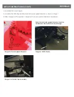
Image 5: Crank Support Bracket
Image 7: A Frame Top Assembly
Note: Hand crank support bracket must be
installed on the bottom of chute flange.
Image 6: Hitch Frame
4. Assemble hitch, see Image 6.
5. Assemble the hitch top assembly and chute crank support brackets as shown in image 7.
6. Refer to page 2 of the operator’s manual for final service and installation of snowblower.
BE-SBSxxG
Содержание BE-SBS G Series
Страница 9: ...SNOWBLOWER DIAGRAM BE SBSxxG...
Страница 15: ......

