background image

SET UP INSTRUCTIONS

1. Un-crate items and compare with the parts breakdown found in the Operator’s Manual.

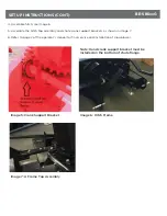
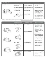
2. Bolt on left and right skid shoes according to Image 1.

3. Assemble the chute. Following manner of assembly in Image 2 and Image 3. Refer to the snowblower

    diagram in the diagram in the operator’s manual for exploded view.

Image 1: Assembled Skid Shoe.

Image 2: Chute Assembly.

Image 4: Chute Bearing.

Note: Shims (#24 in parts list) for 

bearings must be installed on the top

bottom of bearings.

The bolts must be oriented with the 

threads down, see Image 4.

Image 3: Chute Assembly.

BE-SBSxxG

Содержание BE-SBS G Series

Страница 1: ...BE SBSxxG Snowblower Manual Operations Parts Manual BE SBS50G BE SBS60G BE SBS72G BE SBS76G BE SBS7680G For Models Purchase Date Dealer Model No Serial No...

Страница 2: ...r unit to ground level shut off engine make sure all moving parts have stopped and all pressure in the hydraulic system is relieved 7 Do not attempt to remove any obstruction from discharge chute unti...

Страница 3: ...attached securely at both ends before operating SAFETY DECALS BE SBSxxG To keep your blower in good operating condition please inspect and re tighten as necessary any loose nuts or studs after a half...

Страница 4: ...which can be a danger to nearby persons pets livestock or buildings Decreasing the length of the top link causes the blower to ride back on the skid shoes raising the cutting height thereby reducing...

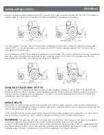
Страница 5: ...nt Please read carefully following instructions which have been specially made to help you and make you satisfied with your purchase PTO SHAFT ANGLES PTO Shafts are made to transmit power with angles...

Страница 6: ...an speed variation as well as a drastic increase of load on cross and bearings To avoid it is recommended to keep tractor PTO Shaft and snowblower input shaft always parallel SHEAR BOLTS Shear bolts a...

Страница 7: ...ng manner of assembly in Image 2 and Image 3 Refer to the snowblower diagram in the diagram in the operator s manual for exploded view Image 1 Assembled Skid Shoe Image 2 Chute Assembly Image 4 Chute...

Страница 8: ...upport bracket must be installed on the bottom of chute flange Image 6 Hitch Frame 4 Assemble hitch see Image 6 5 Assemble the hitch top assembly and chute crank support brackets as shown in image 7 6...

Страница 9: ...SNOWBLOWER DIAGRAM BE SBSxxG...

Страница 10: ...3 23 76 1 Fan 130024 24 1 Flat Washer 3 8 130025 25 1 Bolt 3 8 x1 1 4 130026 26 1 Lock Pin 6x40 130027 27 1 REF NO PART NO DESCRIPTION QTY Nylon Washer 130033 33 1 Special Washer 12x0 2 130034 34 10 B...

Страница 11: ...lastic Shield Assembly 69 888 998 Complete PTO Bondioli Type Series 4 69 888 400 Tractor Yoke 21 10 00 Shearbolt Clutch Series 4 57 117 18 Shearbolt 01 008 045 M8 x 45x1 25 GR8 8 Nut 09 000 008 Nyloc...

Страница 12: ...Excessive Angularity Eliminate interference between guard cones and any part on the tractor and or implement Avoid excessive angle during cornering or when lifting or lowering the implement Replace d...

Страница 13: ...easing instructions Replace defective tubes Extreme load when sliding Short tube engagement Inadequate greasing Continuous sand etc Accelerated wear of telescopic tubes Excessive continuous torque and...

Страница 14: ...cessive shaft length Axial loads too high Excessive working angle and torque Overload caused by high starting and peak torques Excessive working angle Shorten shaft length cut both telescopic tubes as...

Страница 15: ......

Отзывы: