background image

User’s Manual 


IX45GM


41

1.8.11 

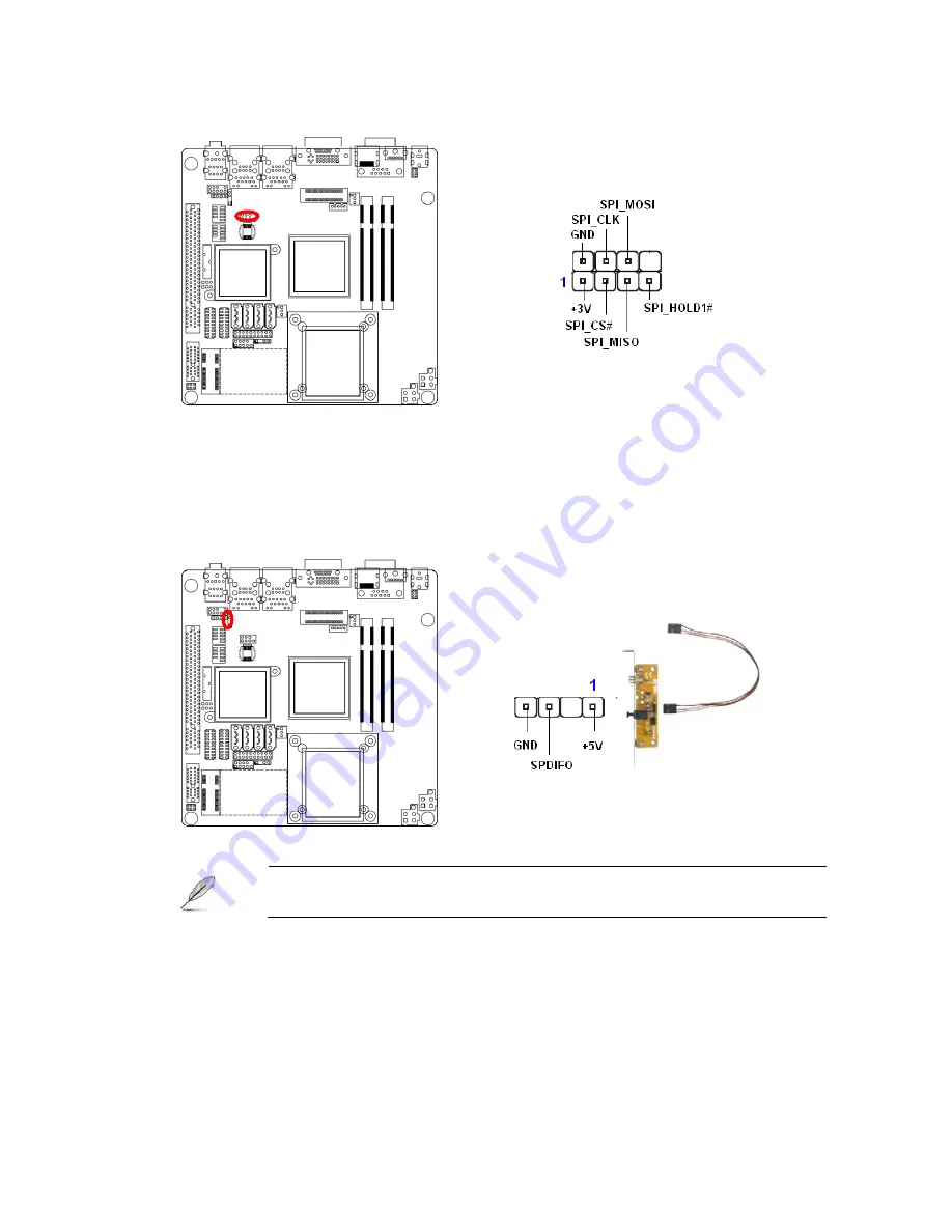
SPI Connector (JSPI1) 


1.8.12 

Digital Audio Connector (SPDIF_OUT1) 

This connector is for an additional Sony/Philips Digital Interface (S/PDIF) port(s). Connect 
the S/PDIF module cable to this connector, then install the module to a slot opening at the 
back of the system chassis. 


The S/PDIF module is purchased separately. 


Содержание IX45GM

Страница 1: ...IX45GM Intel GM45 socket 479P Core Duo Core Solo Core 2 Duo Mini ITX Motherboard User s Manual Ver 1 20...

Страница 2: ...the CPU 19 1 4 2 Installing the CPU Heatsink and Fan 21 1 4 3 Uninstalling the CPU Heatsink and Fan 23 1 5 System Memory 24 1 5 1 SO DIMM Sockets Location 24 1 5 2 Memory Configurations 25 1 5 3 Insta...

Страница 3: ...nnector CPU_FAN1 37 1 8 6 System Fan Connector SYS_FAN1 37 1 8 7 System Panel Connector FPIO1 38 1 8 8 Digital I O Connector 39 1 8 9 LVDS Connector JLVDS1 39 1 8 10 LCD Inverter Connector JBKL1 40 1...

Страница 4: ...al power company z If the power supply is broken do not try to fix it by yourself Contact a qualified service technician or your retailer Operation safety z Before installing the motherboard and addin...

Страница 5: ...S updates driver updates and other information http www bcmimb com tw Conventions Used in This Guide To make sure that you perform certain tasks properly take note of the following symbols used throug...

Страница 6: ...ni ITX Motherboard 9 1 x CD ROM contains the followings User s manual this manual in PDF file Drivers 9 1 x 14GS000073V04 COM1 2 cable 9 pin w o bracket 30cm 1 0mm pitch 9 2 x 14G000127073 SATA cable...

Страница 7: ...User s Manual IX45GM 7 Revision History Revision Revision History Date V 1 0 First release for PCB 1 00 July 11 2009...

Страница 8: ...verheats Expansion Slots 1 x PCI slot PCI Rev 2 2 compliant supports 3 PCI master 1x PCI E x1 Slot S3 S3 Support SmartFan Control Yes I O MIO 4 x SATA 8 x USB 4 x RS 232 1 x K B 1 x Mouse COM1 2 with...

Страница 9: ...2 Intel 82574L PCI E Gigabit Ethernet Controller optional Jumpers Label Function Note CLRTC1 Clear CMOS Normal Clear CMOS SPDIF_OUT1 AAFP1 Front Panel Audio Connector Connectors Label Function Note JA...

Страница 10: ...IX45GM 10 Connectors JLVDS1 LVDS Connector COMPWR2 COMPWR3 COM1 COM2 RI 5V 12V Selection 12V Ring 5V COM23 COM45 COM Connector Specifications are subject to change without notice...

Страница 11: ...User s Manual IX45GM 11 Block Diagram...

Страница 12: ...IX45GM 12 This chapter describes the motherboard features and the new technologies it supports 1 Product introduction 1 Product introduction...

Страница 13: ...object such as the power supply case before handling components to avoid damaging them due to static electricity z Hold components by the edges to avoid touching the ICs on them z Whenever you uninst...

Страница 14: ...can cause you physical injury and damage motherboard components 1 2 1 Placement Direction When installing the motherboard make sure that you place it into the chassis in the correct orientation The ed...

Страница 15: ...User s Manual IX45GM 15 1 3 Motherboard Layout...

Страница 16: ...2 00mm 32 JCOMPWR2 COM 2 RI 5V 12V selection 3 x 2 header pitch 2 00mm 32 CHASSIS1 Chassis intrusion 4 x 1 header pitch 2 54mm 32 Rear Panel Connector Label Function Note Page KBMS1 PS 2 keyboard and...

Страница 17: ...1 wafer pitch 2 54mm 36 FPIO1 System panel connector 5 x 2 header pitch 2 54mm 37 JDIO1 Digital I O connector 10 x 2 header pitch 2 00m 38 JLVDS1 LVDS connector HIROSE DF13S 40DP 1 25V 38 JBKL1 LCD In...

Страница 18: ...ntion mechanism If the instructions in this section do not match the CPU documentation follow the latter z Upon purchase of the motherboard make sure that the PnP cap is on the socket and the socket c...

Страница 19: ...talling the CPU 1 Locate the CPU socket on the motherboard Before installing the CPU make sure that the socket box is facing towards you 2 The processor socket comes with a screw to secure the process...

Страница 20: ...ly insert the CPU into the socket until it fits in place Gold mark 5 Turn the screw to the lock position The CPU fits in only one correct orientation DO NOT force the CPU into the socket to prevent be...

Страница 21: ...sembly If you buy a CPU separately make sure that you use only Intel certified multi directional heatsink and fan If you purchased a separate CPU heatsink and fan assembly make sure that you have prop...

Страница 22: ...e to the connector on the motherboard labelled CPU_FAN1 z Do not forget to connect the fan cables to the fan connectors Insufficient air flow inside the system may damage the motherboard components an...

Страница 23: ...e each fastener counterclockwise 3 Pull up two fasteners at a time in a diagonal sequence to disengage the heatsink and fan assembly from the motherboard 4 Carefully remove the heatsink and fan assemb...

Страница 24: ...Data Rate 2 DDR2 SO DIMM sockets A DDR2 module has the same physical dimensions as a DDR SO DIMM but has a 200 pin footprint compared to the 184 pin DDR DIMM DDR2 SO DIMMs are notched differently to p...

Страница 25: ...ibility it is recommended that you obtain memory modules from the same vendor z Due to chipset resource allocation the system may detect less than 1 GB system memory when you installed one 1 GB DDR2 m...

Страница 26: ...of touching its connectors 3 Align the notch key on the module with the rib on the slot 4 Firmly press the modules into the socket automatically snaps into the mounting notch Do not force the SO DIMM...

Страница 27: ...DIMM 1 Press the two ejector tabs on the slot outward simultaneously and then pull out the SO DIMM module Support the SO DIMM lightly with your fingers when pressing the ejector tabs The SO DIMM migh...

Страница 28: ...rd 2 Remove the system unit cover if your motherboard is already installed in a chassis 3 Remove the bracket opposite the slot that you intend to use Keep the screw for later use 4 Align the card conn...

Страница 29: ...ct to IRQ 9 3 11 IRQ holder for PCI streering 4 12 Communications Port COM1 5 13 IRQ holder for PCI streering 6 14 Floppy Disk Controller 7 15 Printer Port LPT 8 3 System CMOS Rear Time 9 4 IRQ holder...

Страница 30: ...a LAN card installed on a PCI slot 1 6 5 PCI Express x1 This motherboard supports PCI Express x1 network cards SCSI cards and other cards that comply with the PCI Express specifications The figure sho...

Страница 31: ...To erase the RTC RAM 1 Turn OFF the computer and unplug the power cord 2 Remove the onboard battery 3 Move the jumper cap from pins 1 2 default to pins 2 3 Keep the cap on pins 2 3 for about 5 10 sec...

Страница 32: ...IX45GM 32 1 7 2 COM1 RI 5V 12V Selection JCOMPWR3 JCOMPWR3 5V Default 12V Ring 1 7 3 COM2 RI 5V 12V Selection JCOMPWR2 JCOMPWR2 5V Default 12V Ring...

Страница 33: ...or This port allows Gigabit connection to a Local Area Network LAN through a network hub Refer to the table below for the LAN port LED indications The optional 10 100 1000 Mbps LAN controller allows 1...

Страница 34: ...on of this port becomes Front Speaker Out 7 AUDIO1 Microphone port Pink This port connects a microphone 8 USB1 USB2 USB 2 0 connector These four 4 pin Universal Serial Bus USB ports are available for...

Страница 35: ...provide 8A on the 12V lead and at least 1A on the 5 volt standby lead 5VSB The minimum recommended wattage is 230W or 300W for a fully configured system The system can become unstable and might experi...

Страница 36: ...IX45GM 36 1 8 3 Serial Port 2 3 Connector COM2 COM3 1 8 4 Serial Port 4 5 Connector COM4 COM5...

Страница 37: ...ccur if you fail to plug this connector z These are not jumpers DO NOT place jumper caps on the fan connectors 1 8 6 System Fan Connector SYS_FAN1 z Do not forget to connect the fan cables to the fan...

Страница 38: ...for the system power button Pressing the power button turns the system on or puts the system in sleep or soft off mode depending on the BIOS settings Pressing the power switch for more than four secon...

Страница 39: ...User s Manual IX45GM 39 1 8 8 Digital I O Connector 1 8 9 LVDS Connector JLVDS1...

Страница 40: ...IX45GM 40 1 8 10 LCD Inverter Connector JBKL1 z Signal Description Signal Signal Description VR Bright adjust Vadj 0 75V 4 25V Recommended 4 7K 1 16W ENBKL LCD backlight ON OFF control signal...

Страница 41: ...Connector SPDIF_OUT1 This connector is for an additional Sony Philips Digital Interface S PDIF port s Connect the S PDIF module cable to this connector then install the module to a slot opening at th...

Страница 42: ...4 SATA1 SATA2 SATA3 SATA4 z Install the Windows 2000 Service Pack 4 or the Windows XP Service Pack1 before using Serial ATA z When using the connectors in Standard IDE mode connect the primary boot ha...

Страница 43: ...connectors are for USB 2 0 ports Connect the USB GAME module cable to any of these connectors then install the module to a slot opening at the back of the system chassis These USB connectors comply w...

Страница 44: ...IX45GM 44 2 This chapter tells how to change the system settings through the BIOS Setup menus Detailed descriptions of the BIOS parameters are also provided BIOS Setup...

Страница 45: ...loppy Drive icon d Click File from the menu then select Format A Format 3 1 2 Floppy Disk window appears e Select Create an MS DOS startup disk from the format options field then click Start Windows 2...

Страница 46: ...Load Default Settings item under the Exit Menu See section 2 9 Exit Menu z The BIOS setup screens shown in this section are for reference purposes only and may not exactly match what you see on your s...

Страница 47: ...n initial list of configurable items in the menu you selected 2 2 3 Sub menu Note that a right pointer symbol X appears to the left of certain fields This pointer indicates that you can display a sub...

Страница 48: ...n BIOS Setup screen is shown below y System Time System Date Use this option to change the system time and date Highlight System Time or System Date using the Arrow keys Enter new values through the k...

Страница 49: ...using the Arrow keys All Advanced BIOS Setup options are described in this section The Advanced BIOS Setup screen is shown below The sub menus are described on the following pages CPU Configuration S...

Страница 50: ...led y Adjacent Cache Line Prefetch The choices of Adjacement Cache Line Prefetch which automatically fetches an extra 64 byte cache line are Enabled Disabled y Max CPUID Value Limit The choices of Max...

Страница 51: ...cessing The item is to enable or disable the Core Multi processing function y Intel SpeedStep tech The choices of Execute Disable Bit Capability are Enabled Disabled y Intel C State tech The choices o...

Страница 52: ...the selected option A description of the selected item appears on the right side of the screen The settings are described on the following pages y Mirrored IDER Configuration The choices of Mirrored I...

Страница 53: ...oard IDE controllers are set to a specific IDE disk drive in the AMIBIOS 5 Set this value to stop the AMIBIOS from searching the IDE bus for IDE disk drives in five seconds A large majority of ultra A...

Страница 54: ...IX45GM 54 AHCI Configuration AHCI BIOS Support Enables for supporting AHCI BIOS The choices are Enabled or Disabled...

Страница 55: ...elow y Serial Port1 Address This option specifies the base I O port address and Interrupt Request address of serial port 1 The Optimal setting is 3F8 IRQ4 Option Description Disabled Set this value to...

Страница 56: ...serial device connected to this port is an external modem If the system will not use an external modem set this port to Disabled Note Most internal modems require the use of the second COM port and us...

Страница 57: ...he default setting If the system will not use a serial device it is best to set this port to Disabled y Serial Port5 Address This option specifies the base I O port address of serial port 5 The Optima...

Страница 58: ...ed option The settings are described on the following pages The screen is shown below y Chassis Intrusion This item selects the chassis intrusion The choices are Disabled or Enabled y System Temperatu...

Страница 59: ...re 3VCC 12V 5V 5VSB 3VSB VBAT This shows the voltage of VCORE 3VCC 12V 5V 5VSB V 3VSB V and VBAT V y CPU Smart Fan The options are Disabled Silent mode Optimal mode and Performance mode y System Smart...

Страница 60: ...elect an item Use the Plus and Minus keys to change the value of the selected option The settings are described on the following pages The screen is shown below y General ACPI Configuration This item...

Страница 61: ...you to select the suspend type under the ACPI operating system Option Description S1 POS Power on Suspend S3 STR Suspend to RAM Auto POS STR y Repost Video on S3 Resume Determines whether to invoke VG...

Страница 62: ...ble or disabled the USB resume from S3 S4 status y High Performance Event Timer This item allows you to enable or disable the High Performance Event Timer y HPET Memory Address This item allows you to...

Страница 63: ...the up and down Arrow keys to select an item Use the Plus and Minus keys to change the value of the selected option The settings are described on the following pages The screen is shown below y AHCI...

Страница 64: ...etected connected device y SATA Port0 1 2 3 4 5 This item allows you to select the connected device type Options Auto Default y S M A R T This item allows you to control the device S M A R T function...

Страница 65: ...d option The settings are described on the following pages y Restore on AC Power Loss This item allows you to set AC Power Loss to Power Off Power On or Last State y Resume On Ring Disable or Enable R...

Страница 66: ...gy AMT is hardware based technology for remotely managing and securing PCs out of band The options are Disabled Enabled z Force IDE Force SOL SOL IDER Serial Over LAN IDE Redirection is a protocol def...

Страница 67: ...ntel TXT LT settings Use the up and down Arrow keys to select an item Use the Plus and Minus keys to change the value of the selected option The settings are described on the following pages The scree...

Страница 68: ...r the Intel VT d settings Use the up and down Arrow keys to select an item Use the Plus and Minus keys to change the value of the selected option The settings are described on the following pages The...

Страница 69: ...ntel Trusted Computing settings Use the up and down Arrow keys to select an item Use the Plus and Minus keys to change the value of the selected option The settings are described on the following page...

Страница 70: ...ighting it using the Arrow keys All Plug and Play BIOS Setup options are described in this section The Plug and Play BIOS Setup screen is shown below 2 5 1 Clear NVRAM This item is to clear NVRAM duri...

Страница 71: ...ts the PCI latency to 128 PCI clock cycles 160 This option sets the PCI latency to 160 PCI clock cycles 192 This option sets the PCI latency to 192 PCI clock cycles 224 This option sets the PCI latenc...

Страница 72: ...etting Reserved This setting allows the specified IRQ to be used by a legacy ISA device 2 5 7 DMA Set this value to allow the DMA setting to be modified The default setting is Available DMA Channel Op...

Страница 73: ...keys All Boot BIOS Setup options are described in this section The Boot BIOS Setup screen is shown below 2 6 1 Boot Settings Configuration You can use this screen to select options for the Boot settin...

Страница 74: ...ip certain POST tests to boot faster y Quiet Boot Set this value to allow the boot up screen options to be modified between POST messages or OEM logo The default setting is Disabled Option Description...

Страница 75: ...to wait on an error for user intervention This setting should be used if there is a known reason for a BIOS error to appear An example would be a system administrator must remote boot the system The c...

Страница 76: ...y Change Supervisor Password The Security Setup screen is shown below The sub menus are documented on the following pages 2 7 1 Change Supervisor Password This item indicates whether a supervisor pas...

Страница 77: ...reen You can select any of the items in the left frame of the screen such as CPU Configuration to go to the sub menu for that item You can display a Chipset BIOS Setup option by highlighting it using...

Страница 78: ...Configuration setup screen varies depending on the supported North Bridge chipset y Boots Graphics Adaptor Priority This item selects which graphics controller to use as the primary boot device The o...

Страница 79: ...is DVMT DVMT Fixed Memory Size Specify the size of DVMT system memory to allocate for video memory The options are 128MB 256MB and Maximum DVMT y Boot Display Device Use the field to select the type o...

Страница 80: ...ved by varying the frequency slightly so that the signal does not use any particular frequency for more than a moment The options Disabled and Enabled y HDCP Support HDCP High Bandwidth Digital Conten...

Страница 81: ...functions IDE channels and PCI slots Use the up and down Arrow keys to select an item Use the Plus and Minus keys to change the value of the selected option y USB Functions Set this value to allow the...

Страница 82: ...t to use HDA controller y SLP_S4 Min Assertion Width The choices are 4 to 5 seconds 3 to 4 seconds 2 to 3 seconds and 1 to 2 seconds y PCIE Ports Configuration Option Description PCIE Port 0 This sett...

Страница 83: ...Exit tab from the setup screen to enter the Exit BIOS Setup screen You can display an Exit BIOS Setup option by highlighting it using the Arrow keys All Exit BIOS Setup options are described in this s...

Страница 84: ...nges select this option to leave Setup and reboot the computer so the new system configuration parameters can take effect Select Exit Saving Changes from the Exit menu and press Enter Save Configurati...

Страница 85: ...this option to quit Setup without making any permanent changes to the system configuration Select Exit Discarding Changes from the Exit menu and press Enter Discard Changes and Exit Setup Now Ok Cance...

Страница 86: ...IX45GM 86 2 9 3 Discard Changes Select Discard Changes from the Exit menu and press Enter Discard Changes Ok Cancel appears in the window Select Ok to discard changes...

Страница 87: ...this option The Optimal settings are designed for maximum system performance but may not work best for all computer applications In particular do not use the Optimal Setup options if your computer is...

Отзывы: