background image

hydroheat.com.au

28

910.026.1 - EN (AUS)

ISTRUCTIONS PERTAINING TO THE INSTALLER

Gas consumption at 15 °C
Natural Gas - 1.13 kPa

POWER HT

1.850

POWER HT

1.1000

POWER HT

1.1200

POWER HT

1.1500

PCI

MJ/m

3

34,02 

34,02 

34,02 

34,02 

Consumption at max. heat output 

m

3

/h

9,26 

10,9

13,08

16,35

Consumption at min. heat output 

m

3

/h

3,50

3,89

4,23

4,39

Gas nozzle

mm

11,5

12

11

11,5

CO

  max. heat output

%

8,7

8,7

8,7

8,7 

CO

2

   min. heat output

%

8,6

8,6 

8,4

8,4

Pout pressure at minimum power

Pa

-

-4

-5

Parameters 

H536-H613

 (rpm) at maximum power

5100

5650 

4650

6000

Parameters 

H541-H610

 (pwm %) at maximum power

90

100 

55

100

Parameter 

H612

 (rpm) at minimum power

1900

2100 

1600

1550

Parameter 

H609

 (pwm) at minimum power

15

15 

10

9,5

Parameter 

H611

 (rpm) ignition load

3600

3600 

2600

2900

Length of exhaust flue : 0 ÷ 10 m

Parameter 

H608

 (pwm) ignition load

30

30 

15

15

Length of exhaust flue : 10 ÷ 20 m

Parameter 

H608

 (pwm) ignition load

40

40 

20

20

Cascade solution with single clapet Ø 110/110

Parameters 

H536-H613

 (rpm) at maximum power

5500

6000 

Parameter 

H612

 (rpm) at minimum power

2200

2250 

Parameter 

H609

 (pwm) at minimum power

16,5

16 

Parameter 

H608

 (pwm) ignition load

40

40 

Table 2.1

Gas consumption at 15 °C
Propane Gas - 2.75 kPa

POWER HT

1.850

POWER HT

1.1000

POWER HT

1.1200

POWER HT

1.1500

PCI

MJ/Kg

46,34 

46,34 

46,34 

46,34

Consumption at max. heat output 

Kg/h

6,77 

7,97

9,56

11,95

Consumption at min. heat output 

Kg/h

2,57

2,86

3,10

3,22

Gas nozzle

mm

7,8

7,8

7,8

7,8

CO

  max. heat output

%

10,2

10,2

10,2

10,2

CO

2

   min. heat output

%

9,3

9,8

10,2

10,2

Pout pressure at minimum power

Pa

-

-7

-8

Parameters 

H536-H613

 (rpm) at maximum power

4600

5150 

4300

5350

Parameters 

H541-H610

 (pwm %) at maximum power

90

100 

55

100

Parameter 

H612

 (rpm) at minimum power

1900

1950 

1450

1450

Parameter 

H609

 (pwm) at minimum power

14,5

14,5 

10

9,5

Parameter 

H611

 (rpm) ignition load

4200

4200 

2600

2900

Length of exhaust flue : 0 ÷ 10 m

Parameter 

H608

 (pwm) ignition load

40

40 

15

15

Length of exhaust flue : 10 ÷ 20 m

Parameter 

H608

 (pwm) ignition load

50

50 

20

20

Cascade solution with single clapet Ø 110/110

Parameters H536-H613 (rpm) at maximum power

5000

5500 

Parameter H612 (rpm) at minimum power

2200

2100 

Parameter H609 (pwm) at minimum power

16,5

16 

Parameter H608 (pwm) ignition load

50

50 

Table 2.2

Содержание Power HT 1.1000

Страница 1: ...oilers Installation operation and maintenance Manual EN AUS Hydroheat Supplies Pty Ltd PO Box 1045 6 Helen Kob Drive Braeside VIC 3195 Ph 03 9588 1299 Fax 03 9588 2199 0085 Floor standing condensing gas boilers Installation operation and maintenance Manual EN AUS Hydroheat Supplies Pty Ltd PO Box 1045 6 Helen Kob Drive Braeside VIC 3195 Ph 03 9588 1299 Fax 03 9588 2199 ...

Страница 2: ... are a potential source of danger BAXI S p A declares that these models of boiler bear the CE mark in compliance with the basic requirements of the following Directives Gas Directive 2009 142 EC Ef ciency Directive 92 42 EEC Electromagnetic Compatibility Directive 2004 108 EC Low Voltage Directive 2006 95 EC BAXI S p A a leading European manufacturer of hi tech boilers and heating systems has deve...

Страница 3: ...ions prior to installation 12 10 Boiler installation and dimensions 13 11 Chimney ue connection 17 12 Connecting the mains supply 19 13 Adjusting the gas valves and gas change 25 14 Setting the boiler parameters 29 15 Control and operation devices 30 16 Positioning of the ignition and ame sensing electrode 31 17 Check of combustion parameters 31 18 Activating the ue sweeper function 32 19 Annual s...

Страница 4: ...ducts To avoid damaging metal plastic and rubber parts use only neutral cleaners i e non acid and non alkaline The recommended products for cleaning are SENTINEL X300 or X400 and FERNOX heating circuit restore To use this product proceeding strictly in accordance with the maker s directions 1 2 existing system Before proceeding with installation of the boiler the system must be cleaned and flushed...

Страница 5: ...OF THE BOILER KEYS DISPLAY SYMBOLS Central heating mode setting key Data display reset key Parameter setting key increase value Parameter setting key decrease value Program access and scroll key Program access and scroll keys Reset key Domestic hot water temperature setting key Central heating water temperature setting key Domestic hot water on off key Resettable alarm warning Flame present on Out...

Страница 6: ...t 3 7 Faults and resetting the boiler the boiler can be restarted by pressing this key for at least two seconds If this key is pressed with no fault present the display will show the message E153 and the same key has to be pressed again for at least two seconds to restart the boiler 9 Data key This key can be pressed repeatedly to display the following information Temperature C of the domestic hot...

Страница 7: ... 1 to set the central heating water temperature Press the keys to set the temperature required press either of the keys 1 or 10 figure 1 to save and return to the main menu N b With the outdoor sensor connected the key 2 figure 1 can be used to shift the central heating curve Press the keys to decrease or increase the room temperature in the premises to be heated 3 3 SETTING THE MAXIMUM CENTRAL HE...

Страница 8: ...ily times for domestic hot water mode operation Factory setting of D H W function is enable ON while is disabled D H W daily times program To enable D H W daily times program see section 14 parameter H91 Setting the daily times for domestic hot water mode operation Carry out the operations described in section 3 5 1 for program lines 31 to 36 3 6 SETTING THE MINIMUM CENTRAL HEATING TEMPERATURE pre...

Страница 9: ...stic hot water production 0 00 00 00 24 00 P35 Start of third daily period of domestic hot water production 0 00 00 00 24 00 P36 Fine End of third daily period of domestic hot water production 0 00 00 00 24 00 P45 Reset of daily central heating and domestic hot water production programs factory settings Press the keys together for about 3 seconds the number 1 appears on the display Con rm by press...

Страница 10: ...10 Safety or fumes thermostat or heating return temperature probe tripped press the reset key for about 2 seconds if this device is triggered repeatedly call the authorised service centre E111 Delivery temperature higher than 95 C If this fault persists call the authorised service centre E128 Loss of flame during operation the ionization current has fallen below the limit Call an authorised servic...

Страница 11: ... and is therefore exposed to danger of frost we suggest you add some speci c purpose anti freeze to the water contained in the system e g propylene glycole coupled with corrosion and scaling inhibitors The electronic management of boilers includes a frost protection function in the central heating system which operates the burner to reach a heating flow temperature of 30 C when the system heating ...

Страница 12: ...the user section Note that installation maintenance and operation of the gas appliances must be performed exclusively by quali ed personnel in compliance with current standards Please note the following Install the boiler in a permanent ventilated central heating boiler room This boiler can be connected to any type of convector plates radiators thermoconvectors Design the system sections as usual ...

Страница 13: ... sewer not plastic To drain the boiler use the drain tap at the rear N B Take special care when filling the heating system In particular open any thermostat valves in the system ensure the water enters slowly in order to prevent the formation of air inside the primary circuit until operating pressure is reached Lastly vent any radiators in the system BAXI declines all liability for damage deriving...

Страница 14: ...l 1 850 801 850 450 G 3 4 G 1 G 1 13 7 1 1000 871 850 450 G 1 G 1 1 4 G 1 1 4 21 1 1200 1024 850 450 G 1 G 1 1 4 G 1 1 4 23 3 1 1500 1132 850 450 G 1 G 1 1 4 G 1 1 4 25 3 Table 1 Figure 5 MR heating flow RR heating return GAS gas inlet to the boiler SC condensate drain Insert the flue gas union and fasten the connector to the flue gas thermo stat CT_0806 0902_2501 SC GAS RR MR ...

Страница 15: ...del Minimum water flow rate l h Water flow rate with t 20 K l h 1 850 1900 3700 1 1000 2100 4300 1 1200 2600 5200 1 1500 3300 6500 10 1 BOILER PRESSURE LOSS Figure 6 CONDENSATE DRAIN For the choice of water sepa rator refer to the declaration made by the manufacturer according to the water flow rates given in the table below CT_0807 7 0902_2502 ...

Страница 16: ... TO THE INSTALLER Exchangers pressure drop mH 2 O WATER FLOW RATE l h Graph 1 0502_2105 POWER HT 1 850 1 1000 EXCHANGERS PRESSURE DROP POWER HT 1 1200 1 1500 EXCHANGERS PRESSURE DROP Exchangers pressure drop mH 2 O WATER FLOW RATE l h Graph 1 1 0601_2008 120 kW ...

Страница 17: ...llations are available diameter 110 mm 11 CHIMNEY FLUE CONNECTION 11 1 CONNECTOR WITH B23 TYPE Figure 7 CT_0809 0902_2705 CT0667 0903_1601 In case exhaust and intake flues not supplied by BAXI S p A have been installed these must be certified for the type of use and must have a maximum pressure drop in according to the values reported in the table To ensure the correct rated heat input to the maxi...

Страница 18: ...1000 150 110 HT 1 1200 170 80 HT 1 1500 280 120 WARNING To guarantee more operating insurance it is necessary to assure the flue pipes to the wall using the apposite clamps The kit is used to introduce combustion air from outside the installation area and comprises a hose to be installed in the venturi body Please consult the instructions supplied with the kit For air ducts diameter and length see...

Страница 19: ...ed to the appliance is less than 2 A If the value is greater a relay must be wired between the boiler control circuit board and the accessories drawing the higher current 12 1 TERMINAL BLOCKS ACCESS Cut off power to the boiler with the two pole switch Remove the top facia panel cover which is held by magnets Unscrew the two screws holding the facia panel in place Swing the facia panel forwards Mai...

Страница 20: ...tions provided with the temperature regulator to ensure correct installation and programming Terminals 3 4 room temperature thermostat TA Thermostats with integral accelerator resistor must not be used Check that there is no voltage across the ends of the two thermostat connection wires Terminals 5 6 floor temperature thermostat connection TP commercially available device Check that there is no vo...

Страница 21: ... the QAA73 temperature regulator for the user parameter programming procedure fault messages In the event of fault the display panel on the QAA73 shows the flashing symbol Press the information key to display the error code and a description of the fault see table on paragraph 3 9 Line no Parameter Range Default value 70 HC1 gradient Selection of central heating circuit temperature curve kt 2 5 40...

Страница 22: ...e curve Kt 15 Increase the value displayed if the room temperature required is not reached inside the premises for central heating b with QAA73 room temperature regulator The temperature curve kt must be selected by setting parameter 70 HC1 curve of the QAA73 room tem perature control device as described in section 12 4 QAA73 parameters which can be set by the installation service engineer See gra...

Страница 23: ... the room controlled by the QAA73 temperature control device must be supplied with electricity by means of terminals 11 12 of terminal block M3 in gure 10 The contact relating to the request for operation of the other zones must be parallel connected and connected to terminal 3 4 TA of terminal block M2 in gure 10 The jumper present must be removed The central heating temperature of the zone contr...

Страница 24: ... device must be located in the pocket provided on the storage tank gure 11 The temperature and on off programming of the domestic hot water supply are selected directly from the boiler control panel as described in this manual under the user instruction headings 12 7 DOMESTIC HOT WATER CIRCUIT ELECTRIC PUMP CONNECTIONS If the installation is divided into zones a relay has to be de activated to swi...

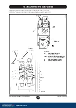
Страница 25: ...ve a single gas valve gure 12 a POWER HT models 1 1200 and 1 1500 have a double gas valve gure 12 b 0502_2108 Figure 12a LEGEND Pi Gas supply pressure connection point P out Pressure connection point for measurement of the OFFSET V Gas flow adjuster screw K OFFSET adjuster screw 0502_2109 Figure 12b gas nozzle gas nozzle mixer gas manifold ...

Страница 26: ...CO2 level Turn the screw anti clockwise to decrease the CO2 level Proceed as follows to adjust the double gas valve Connect a pressure gauge to the P1OUT pressure measurement hole on valve 1 Insert the probe of the flue gas analyzer in the sampling port as indicated in heading 17 gure 15 Switch on the boiler activating the setting function from the control panel by pressing and holding the and key...

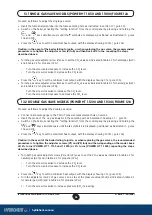
Страница 27: ...ollowing operation must be carried out before proceeding to adjust the gas valve as described above For models with one valve replace the diaphragm on the gas valve outlet gure 12a To replace the diaphragm disassemble the gas valve by undoing the inlet and outlet ttings then unscrew the nozzle with a pair of straight round nose pliers Check the fluid tightness of the gas ttings removed previously ...

Страница 28: ...meter H612 rpm at minimum power 2200 2250 Parameter H609 pwm at minimum power 16 5 16 Parameter H608 pwm ignition load 40 40 Table 2 1 Gas consumption at 15 C Propane Gas 2 75 kPa POWER HT 1 850 POWER HT 1 1000 POWER HT 1 1200 POWER HT 1 1500 PCI MJ Kg 46 34 46 34 46 34 46 34 Consumption at max heat output Kg h 6 77 7 97 9 56 11 95 Consumption at min heat output Kg h 2 57 2 86 3 10 3 22 Gas nozzle...

Страница 29: ...re curve of central heating circuit HC1 see Graph 1 15 H533 Selection of temperature curve of central heating circuit HC2 see Graph 1 15 H608 PWM Setting Ignition load See table 2 H611 Speed setting rpm Ignition load H609 PWM Setting minimum power H541 H610 PWM Setting maximum power Central heating Domestic hot water H612 Speed setting rpm minimum power H536 H613 Speed setting rpm maximum power Ce...

Страница 30: ...ause of the trip press the reset button positioned on the thermostat itself then press the release button on the boiler It is forbidden to disenable this safety device Flame ionization detector The ame sensing electrode guarantees safety of operation in case of gas failure or incomplete interlighting of the main burner Under such conditions the boiler is locked out You must press the reset button ...

Страница 31: ...concentration Carbon monoxide CO concentration Measure the temperature of combustion air near the air inlet to the boiler The necessary hole must be made by the technician responsible for the heating system when the system is first started up and must then be closed to ensure that the ue remains properly sealed during normal operation 17 CHECK OF COMBUSTION PARAMETERS 16 POSITIONING OF THE IGNITIO...

Страница 32: ...rols check the appearance and airtightness of the gaskets of the gas and combustion circuits check the state and correct position of the ignition and flame sensing electrodes check the state of the burner and make sure it is rmly xed check for any impurities inside the combustion chamber Use a vacuum cleaner to do this check the gas valve is correctly calibrated check the pressure of the heating s...

Страница 33: ...ng probe 4 105 C overheat safety thermostat 5 gas valve 6 flue water exchanger 7 flame detector electrode 8 burner 9 ignition electrode 10 mixer with venturi 11 gas diaphragm 12 fan 13 flue joint 14 automatic air vent 15 hydraulic pressure sensor 16 boiler drain point 17 joint flue with flue thermostat 18 flue thermostat 19 seat of air intake pipe 20 NTC return heating probe ...

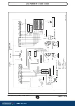
Страница 34: ...WER TERMINAL BOARD FUSE CENTRAL HEATING SYSTEM PUMP CONNECTION POINTS DOMESTIC HOT WATER PUMP CONNECTION POINTS SAFETY THERMOSTAT FLAME SENSING ELECTRODE NTC RETURN HEATING PROBE ROOM THERMOSTAT QAA73 CONNECTION FLOOR TEMPERATURE THERMOSTAT CONNECTION OUTSIDE SENSOR D H W STORAGE THANK SENSOR IGNITION ELECTRODE HYDRAULIC PRESSURE SENSOR IGNITER GAS VALVE FAN MAINS POWER 230 V 50 Hz FLUE THERMOSTAT...

Страница 35: ...AT QAA73 CONNECTION FLOOR TEMPERATURE THERMOSTAT CONNECTION OUTSIDE SENSOR D H W STORAGE THANK SENSOR HYDRAULIC PRESSURE SENSOR GAS VALVE 2 FLUE THERMOSTAT SAFETY THERMOSTAT CENTRAL HEATING SYSTEM PUMP CONNECTION POINTS DOMESTIC HOT WATER PUMP CONNECTION POINTS MAINS POWER TERMINAL BOARD FUSE CT_0823 0912_1002 NTC RETURN HEATING PROBE NTC DELIVERY HEATING PROBE Cables colours C light blue M brown ...

Страница 36: ... Maximum heat output 50 30 C kW 91 6 107 8 129 7 162 kcal h 78776 92708 111542 139320 Minimum heat output 75 60 C kW 32 2 35 8 39 40 4 kcal h 27692 30788 33540 34744 Minimum heat output 50 30 C kW 34 9 38 8 42 1 43 7 kcal h 30014 33368 36206 37582 Useful ef ciency according to 92 42 CEE directive Maximum water pressure kPa 400 400 400 400 Minimum water pressure kPa 50 50 50 50 Heating circuit temp...

Отзывы: