


6.0 System Details
9
6.1
Water Circulating Systems
1. The appliance is suitable for use with open vent
fully pumped systems and sealed systems .
The following conditions should be observed
on all systems:
• The static head must not exceed 30m (100ft)
of water.
• The boiler must not be used with a direct
cylinder.
• Drain cocks should be fitted to all system low
points.
• All gas and water pipes and electrical wiring
must be installed in a way which would not
restrict the servicing of the boiler.
• Position isolating valves as close to circulating
pump as possible.
• It is recommended that the return pipe is fitted
with an automatic air vent as close to the boiler
as is practical.
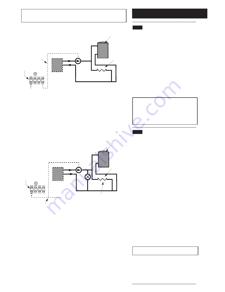
NOTE:
Full TRV Systems (refer to section 6.4)
Where all the radiators are controlled by TRV’s
then pump protection will be required. This can be
done by either of the options opposite (see Fig A &
B).
The option shown in Fig. A should only be
used on a full TRV system without a bypass.
Fig. B shows a system with a bypass that must
be capable of allowing a flow of at least 3 l/min.
6.2
Treatment of Water Circulating
Systems
• All recirculatory water systems will be subject to
corrosion unless an appropriate water treatment
is applied. This means that the efficiency of
the system will deteriorate as corrosion sludge
accumulates within the system, risking damage
to pump and valves, boiler noise and circulation
problems.
• When upgrading existing systems that exhibit
evidence of sludging, it is advisable to clean the
system prior to treatment in order to remove any
sludge and reduce the likelihood of these
deposits damaging new components.
• When fitting new systems flux will be evident
within the system, which can lead to damage of
system components.
• All systems must be thoroughly drained and
flushed out. The recommended flushing and
cleansing agents are Betz-Dearborn Sentinel
X300 or X400 and Fernox Superfloc Universal
Cleanser which should be used following the
flushing agent manufacturer’s instructions.
• System additives - corrosion inhibitors and
flushing agents/descalers should be suitable for
aluminium and comply to BS7593 requirements.
The only system additives recommended are
Betz-Dearborn Sentinel X100 and Fernox-Copal
which should be used followng the inhibitor
manufacturer’s instructions.
Failure to flush and add inhibitor to the
system will invalidate the appliance warranty.
• It is important to check the inhibitor
concentration after installation, system
modification and at every service in accordance
with the manufacturer’s instructions. (Test kits
are available from inhibitor stockists.)
• For information or advice regarding any of the
above contact the Baxi Helpline.
Boiler
No demand
for hot water
Central
heating
load
All TRV’s shut down
(boiler flow switch
causes pump to stop)
Live feed
to pump
Switch live from
programmer, etc.
S/L
N P/F
Fig. A Wiring to the pump feed connection of boiler
Fig. B Providing a 3 l/min bypass
Boiler
No demand
for hot water
Central
heating
load
All TRV’s shut down
(pump continues
around bypass)
Switch live from
programmer,
room stat, etc.
S/L
junction
S/L
N P/F
3 l/min
bypass
Boiler
Connections
Boiler
Connections
NOTE:
This boiler does not require a bypass.
This boiler does not require a permanent live.
These diagrams only refer to pump protection for fully TRV’d systems.
Содержание 100 He
Страница 45: ...16 0 Notes 45...
Страница 46: ...16 0 Notes 46...


