background image

Fig. 7b.

Fig. 7c

FIRE LOCATION

The appliance must not be installed in a room or
space, which contains a bath or shower.

This fire is designed for use with either top or rear
flue outlets and must be mounted on a hearth with
a minimum of 12mm non-combustible material
thickness. 

There must be a minimum of 200mm clearance
from the sides of the fire to any combustible
sidewalls. Fig7a.
For clearance from the top of the fire to any
combustible shelf. Fig 7b. (See Graph 1).
There must be a minimum of 230mm from the
rear of the fire to any combustible back wall. 
Fig 7b.

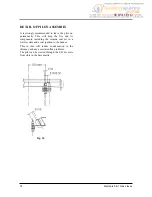
With a 

Non-combustible 

back wall the fire can be

pushed back until the top diverter touches the wall,
although to improve access and air circulation a
minimum distance of 100 mm is recommended. 

Fig 7c.

Reference non-combustible side walls a minimum
of 100mm is recommended.

Do not place any furniture or furnishings (including
curtains) within 1 metre of the fire. 

Memphis 5 & 7 Gas stoves

13

INSTALLATION

non- combustible closure plate,
incorporating access for cleaning debris.

non- combustible closure plate,
incorporating access for cleaning debris.

Fig. 7d.

Содержание Memphis 5

Страница 1: ...ington Birmingham B24 9QP Memphis 5 7 Gas Stoves Operating Installation Manual PLEASE RETAIN THESE INSTRUCTIONS FOR FUTURE REFERENCE FOR USE IN COUNTRIES GB IE REV 1 Memphis 7 Gas Stove Memphis 5 G C No 0504401 Memphis 7 G C No 0504411 ...

Страница 2: ...les service please call 0870 6061064 a Your Post Code b Type of Fire c Model Name d Serial Number e The Fault Problem or Request Memphis 5 7 Gas stoves www baxifires co uk Baxi Fires Division Wood Lane Erdington Birmingham B24 9QP To help us quickly help you please try to have the following information available before you contact us ...

Страница 3: ...ion 13 Combustible Shelf Clearances 14 Hearth Requirements 15 Connecting The Gas Supply 15 Pressure Test Sequence 15 Fire Testing 16 Installation Check List 17 Page SERVICING Details of Pilot Assembly 18 Door Trim 19 Fire Door Glass Seal 19 Burner Assembly 20 Regular Service 20 Annual Service 21 Cleaning Outer Services 21 Cleaning Door Glass 21 Fault Diagnosis 22 SPARE PARTS General Components 23 ...

Страница 4: ... any other debris accumulated in and around the appliance This should be performed before and after the installation It is recommended that any replacement item s are not broken up but sealed within a heavy duty polythene bag and clearly labelled R C F waste This is not classified as hazardous waste and may be disposed of at a tipping site licensed for the disposal of industrial waste Protective c...

Страница 5: ...e on page 4 All surfaces except the control knob the control door handle and control door are considered to be working surfaces Warning Under no circumstances must the fire be operated if the glass is cracked or broken Warning If it is known or suspected that an operational or ignition fault exists on the appliance it must not be used until it has been investigated and corrected by a qualified gas...

Страница 6: ...l Gas Memphis 7 Natural Gas Main Burner Injector Max Heat Setting Heat Input net 3 7 kW 5 0 kW Gas Rate 0 391m3 hour 0 529m3 hour Cold Setting Pressure 1 5mb 3 5mb Min Heat Setting 2 4 kW 3 3 kW Bray 82 700 Bray 82 700 Aeromatic AC13 112511 mod 334 Aeromatic AC13 112511 mod 334 Heat Input net Gas Rate 0 254 m3 hour 0 349 m3 hour NOx CLASS CLASS 4 CLASS 4 Fig 2 ...

Страница 7: ...side lining in the right hand side of the fire First position the tall edge into the radius at the front of the fire See Fig 3b below Fig 3b Fitting the R H side lining 3 Then rotate the rear edge until the top faces match up the angle faces at the rear of the fire See Fig 3c Repeat exercise for the left hand side Fig 3c Fitting the side linings 4 Rotate the rear lining to bring it vertical Fig 3d...

Страница 8: ...ild up inside the fire and therefore invalidate the guarantee Ensure the appliance is cold Step 1 Place the base matrix on the matrix plate centrally between the end tabs of the location bar Fig 4a Fig 4a Step 2 Place the rear matrix cut out section over the base matrix and centralise the assembly between the end tabs of the location bar Ensure the rear matrix is pushed back against the location b...

Страница 9: ...and turn anti clockwise to the pilot position Fig 5b Fig 5b Step 1c Keep the control knob pressed in for a further 15 seconds and then release The pilot will remain alight If pilot does not remain alight repeat this procedure Please note that when purging the gas supply it is usual to have to keep the control knob depressed in the spark position for longer periods of time Step 2 To ignite the main...

Страница 10: ... be made to re light the gas for at least three minutes To restart the fire turn the control knob to the off position and repeat the lighting controlling the fire instructions The flame failure device is a safety feature required by law and must not be put out of action by the installer If this device or any of its parts are to be replaced only original manufacturer s parts are to be used Repeated...

Страница 11: ...ght should be between 0 05 and 6mb 0 5mm to 6mm water gauge The Memphis 3 requires a minimum flue size of 100mm 4 inches and the Memphis 4 requires a minimum flue size of 125mm 5 inches If the stove is being connected to a chimney with an inter nal flue size greater than 225mm 9 inches diame ter or 200 x 200mm square a 125mm 5 inches diameter stainless steel flexible flue liner comply ing with BS ...

Страница 12: ...0mm Provide a minimum vertical height of 600mm of flue from the height of the rear flue outlet See figure 7b Closure Plate Connect the flue spigot to the rear outlet Connect a flue extension to the spigot Fit the closure plate in fireplace Position the fire so the flue extension passes through the hole in the closure plate Ensure all joints are suitably sealed See Figure 7c TOP FLUE Provide a mini...

Страница 13: ...ee Graph 1 There must be a minimum of 230mm from the rear of the fire to any combustible back wall Fig 7b With a Non combustible back wall the fire can be pushed back until the top diverter touches the wall although to improve access and air circulation a minimum distance of 100 mm is recommended Fig 7c Reference non combustible side walls a minimum of 100mm is recommended Do not place any furnitu...

Страница 14: ... or other projection made of wood or any other combustible material is shown on graph 1 Graph 1 Combustible Shelf Clearances The recommended minimum height from the extreme top surface of the fire to the underside of a non combustible shelf is 100mm 14 Memphis 5 7 Gas stoves INSTALLATION ...

Страница 15: ... with the 1 4 BSP nut and olive with 8mm tubing A maximum pipe run of 1 5 meters or 5 feet should be adhered to and copper tubing may be used provided a distance of 25mm is maintained between pipe work and any surface of the fire A gas service cock should be fitted adjacent to the fireplace to enable safe removal of the appliance for servicing After fitting the supply operate the gas cock supplied...

Страница 16: ...s not occur the appliance must be disconnected and the flue checked Step 5 If there is an extractor fan in any room this must be turned on and any doors between it and the fire left open repeat the spillage test Repeated operation of the spillage monitoring system indicates that there maybe a flue draw problem In this situation no more attempts at operating the appliance should take place and your...

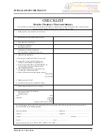
Страница 17: ... gas appliances only c If clay or concrete flue liners used confirm that they are correctly jointed with socket end uppermost and state jointing materials used d If an existing chimney has been refurbished with a new liner type or make of liner fitted e Details of flue outlet terminal and diagram reference Outlet Details Complies with f Number and angle of bends g Provision for cleaning and recomm...

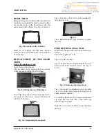
Страница 18: ...e and its components including the ceramic coal set in a warmer state and assist ignition to the burner This in turn will reduce condensation in the chimney and any associated flue problems The pilot can be viewed through the L H centre front slots in the base matrix Fig 10 18 Memphis 5 7 Gas stoves SERVICING ...

Страница 19: ...n a flat surface and remove the single tab The tracery can now be removed See Fig 11c below Fig 11c Untightening the single tab Step 3 The trim will now lift off the remaining 2 tabs See Fig 11d Step 4 Repeat the above steps in reverse to replace the trim FIRE DOOR GLASS SEAL If necessary the glass and seal can be removed as follows Ensure the appliance is cold Step 1 Open the fire door Step 2 The...

Страница 20: ... off posi drive screws just inside the fire door aperture The burner assembly will now lift out After replacement of burner assembly ensure that a check on the gas tightness of any new joint is carried out REGULAR SERVICE See SAFETY NOTICES ref coal set page 4 Any soot debris should be removed from the fuel bed regularly by the end user Ensure the appliance is cold Step 1 Isolate the gas supply fr...

Страница 21: ...ge 4 Step 8 Inspect the pilot assembly to ensure that it is clean unobstructed and in good order Step 9 Check system for gas soundness Step 10 Replace heat shield and matrix location plate Step 11 Replace fire box linings Step 12 Replace coal set Step 13 Replace glass gasket and glass frame and close the fire door Step 14 Carry out spillage test as per instructions on page 16 CLEANING OUTER SURFAC...

Страница 22: ...hermocouple o k No Is the flue blocked Carry out smoke test Is their a spark at the electrode No Is pilot injector obstructed Clean No No No Turn gas on Purge system Yes Correct pressure No Correct alignment or replace No Yes Check piezo igniter Yes Check to ensure the pilot assembly is not obstructed or faulty Yes No Has spillage monitoring system been activated Yes Investigate flue systems Yes N...

Страница 23: ... paint to tone in any connecting flues pipes or surrounding metalwork Tracery or Trim Note When fitted one replaces the other Add on Canopies Memphis 5 Low available only Size 400mm wide x 345mm deep Raises the stove approximately 140mm Memphis 7 High and low are available Size 480mm wide x 345mm deep High Raises the stove approximately 240mm Low Raises the fire approximately 180mm Memphis 5 7 Gas...

Страница 24: ...GS091A AFGS091 AFGS1073 AFGS1073 AFS047 AFS047 1a Memphis 5 Coal Set 2 Co pilot assembly 3 Elbow Injector 4 Gas Control Valve 5 Magnetic Catch for Wonderfire Gas Fires 6 Hinge Kit To Fit either Door Comprises 2 Hinges 4 Fixings Per Set Part Description Visual Aid not to scale Memphis 5 Part No Memphis 7 Part No ...

Страница 25: ...Door Handle Assembly 8 Burner Fixing 9 Pipe Set Complete With Connectors 10 Decorative Door Surround Trim 11 Fire Door Assembly complete with Magnet Lock and Trim 12 Glass Replacement Kit with Gasket Fixings Part Description Visual Aid not to scale Memphis 5 Part No Memphis 7 Part No 13 Hotplate AFGS064 AFGS010 14 Flue Outlet Spigot AFGS1082 AFGS1083 ...

Страница 26: ...ining Kit 16 Large Ceramic Panel Part Description Visual Aid not to scale Memphis 5 Part No Memphis 7 Part No AFGS094 AFGS094 17 Medium Ceramic Panel 18 Small Ceramic Panel AFGS1084 AFGS1084 AFGS025 AFGS025 AFS1125 AFS1125 19 Gas Tap 20 Manual AFS1013 AFS1013 21 Feet and Fixings ...

Страница 27: ...anual please contact your Wonderfire retailer Please keep all repair receipts safely Please ensure you have this manual available when an engineer visits as they will complete the service record chart Memphis 5 7 Gas stoves 27 SERVICE RECORD Date of Visit Company Work Carried Out Signature ...

Страница 28: ...sure installer completes INSTALLATION CHECK LIST details on page 17 of this manual Please ensure the enclosed registration card is completed and returned to Wonderfire and the following information completed for your own information QUALITY FINISH COAL SET REGISTRATION CARD LINING SET FLUE OUTLET HOTPLATE OPERATING INSTRUCTIONS GAS COCK FEET FIXINGS ...

Отзывы: