background image

NE214

48

www.baumer.com

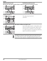
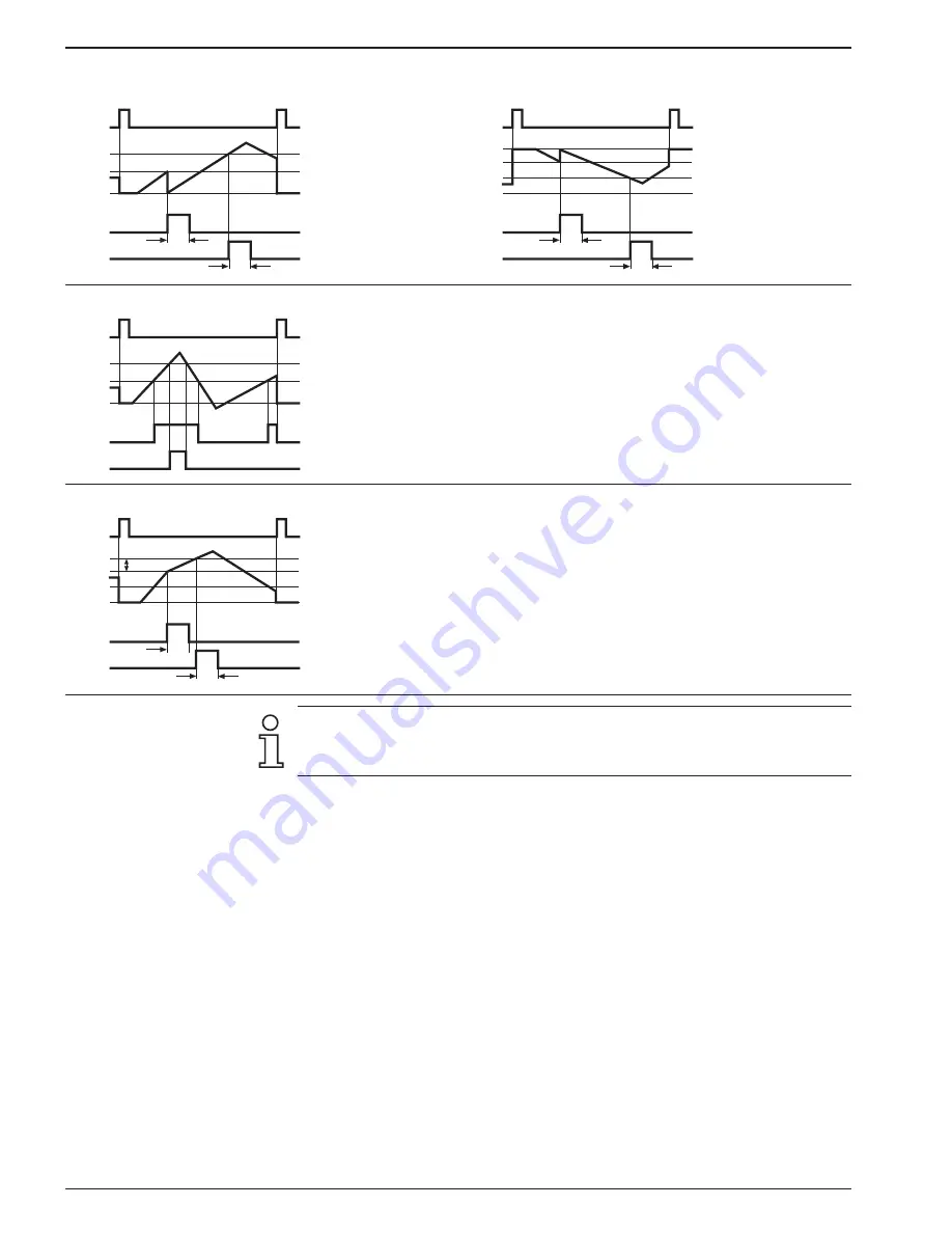
Adding operating mode

Subtracting operating mode

Main preset with pulse signal, without automatic reset (start count value at zero)

RESET

VW (P2)
VW (P1)
O

OUT 1

OUT 2

T

w

T

w

RESET

VW (P1)
VW (P2)

O

OUT 1

OUT 2

SC

T

w

T

w

Parallel comparison

RESET

VW (P2)
VW (P1)
O

OUT 1

OUT 2

The subtracting mode is not
adjustable.

Self-adjusting preset with pulse signal, without automatic reset

RESET

VW (P1)

VW (P2)

O

OUT 1

OUT 2

SC

T

w

T

w

Input of the preset value P1 corresponds to the 
interval between the preliminary signal and the 
final signal. This means that, if the final signal 
(i.e. preset value P2) is changed, the preliminary 
signal is automatically readjusted.

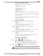
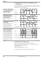
The adding mode is set if the chosen start count value SC is lower 

than preset values P1 and P2. The subtracting mode is set if the 

chosen start count value SC is greater than preset values P1 and P2.

Содержание NE214

Страница 1: ...bezeichnung Baumer IVO GmbH Co KG Dauchinger Strasse 58 62 DE 78056 Villingen Schwenningen Phone 49 7720 942 0 Fax 49 7720 942 900 www baumer com info de baumerivo com Betriebsanleitung Elektronischer...

Страница 2: ...einwandfreiem Zustand verlassen Um diesen Ger te Status zu erhalten ist es erforderlich dass Sie das Ger t bestimmungsgem ss sicherheits und gefahrenbewusst unter Beachtung dieser Betriebsanleitung un...

Страница 3: ...entsprechende Sicherheitsvorkehrungen getroffen werden ffnen Sie nicht das Geh use des Ger tes und nehmen Sie keine Ver nderungen daran vor Manipulationen am Ger t k nnen dessen Funktionssicherheit n...

Страница 4: ...den als Gesamtsummenz hler oder Nebenz hler Betriebsstundenz hler LED Symbolanzeige XP Aktueller Z hlerstand P1 Vorwahlwert 1 P2 Vorwahlwert 2 SC Setzwert Gesammtsummenz hler Betriebsstundenz hler Bed...

Страница 5: ...anschliessen In diesem Kapitel wird Ihnen zuerst die Anschlussbelegung sowie ein Anschlussbeispiel vorgestellt In den Kapiteln 3 1 bis 3 5 finden Sie konkrete Hinweise und tech nische Daten f r die ei...

Страница 6: ...en des Ber hrungsschutzes nach EN 61010 nur mittels Aderendh lsen mit Isolierstoffkappen Vom Werk unbelegte Anschl sse nicht anderweitig belegen Es wird empfohlen alle Sensor Anschlussleitungen abzusc...

Страница 7: ...0 VA W niemals berschritten werden 3 2 Elektronische Ausg nge belegen 13 12 Vorwahl 2 11 10 Vorwahl 1 Die elektronischen Ausg nge Anschl sse 10 11 und 12 13 sind Optokoppler Ausg nge Kollektor und Emi...

Страница 8: ...nschl sse 6 Spur A und 7 Spur B sind Z hleing nge f r den Z hler Die Signal art und Signallogik werden in den Zeilen 25 und 28 programmiert Der Anschluss 8 Reset dient als R ckstelleingang Durch Anleg...

Страница 9: ...uplex bertragung mit den Eigenschaften symmetrisch 4 Leitungen Mehrpunkt Verbindung 1 Sender und 32 Empf nger Daten bertragungsl nge max 1500 m RS485 Halbduplex bertragung mit den Eingenschaften symme...

Страница 10: ...ption mit Analogausgang Anzeigenbeispiele Anzeige Programmnummer version Anzeige Programmdatum Test verschiedener Eingangspegel Schaltschwellen Signalformen und des Phasendiskriminators Test von Numme...

Страница 11: ...P1 Taste dr cken In der Anzeige ist der Vorwahlwert P1 ablesbar Vorwahl P1 ber Tasten und eingeben Vorzeichen nach Freigabe in Zeile 38 m glich Taste dr cken nderung ist beendet ndern Vorwahlwert P2...

Страница 12: ...r sind alle Funktionen vollst ndig beschrieben Funktion in der Bediener und Programmierebene Taste Auf den n chsten Betriebsparameter in der Bediener und Program mierebene umschalten f r Schnelldurchl...

Страница 13: ...ene zur ckgeschaltet Taste dr cken dann Taste dr cken und den korrekten Code eingeben Korrekter Code unbekannt Ist der korrekte Code nicht bekannt das Ger t bitte an das Werk zur ckschicken Korrekter...

Страница 14: ...rd f r die Bedienerebene v llig ge sperrt Bei der Anwahl dieses Betriebsparameters wird dieser in der Bedienerebene nicht angezeigt sondern bersprungen Die entsprechende Funktion bleibt erhalten gespe...

Страница 15: ...hler Skalierungsbereich 0 0001 bis 9999 99 0 1 0000 1 0 0001 2 9999 99 Zeile 24 Dezimalpunkt g ltig f r XP P1 P2 SC 0 kein Dezimalpunkt 1 00000 0 2 0000 00 3 000 000 4 00 0000 Zeile 25 Z hlweise 0 Sp...

Страница 16: ...le 33 Ausgangslogik f r Digitalausg nge 0 beide Ausg nge als Schliesser 1 P1 ffner P2 Schliesser 2 P1 Schliesser P2 ffner 3 beide Ausg nge als ffner Zeile 35 Ausgangszeit P1 0 0 Angaben in Sekunden To...

Страница 17: ...x Zeile 51 Baudrate 0 4800 Baud 1 2400 Baud 2 1200 Baud 3 600 Baud Zeile 52 Parity 0 Even Parity 7 Datenbits 1 Odd Parity 7 Datenbits 2 no Parity 8 Datenbits Zeile 53 Stoppbits 0 1 Stoppbit 1 2 Stoppb...

Страница 18: ...ert und 2 Vorwahlwert abgearbeitet Die Vorwahl werte k nnen beliebig gew hlt werden Eine automatische R ckstel lung auf den Setzwert ist bei dem zweiten Vorwahlwert m glich Eine externe oder manuelle...

Страница 19: ...nz Hauptz hler Spur B 28 Eingangslogik 29 R ckstellung Hauptz hler 31 Funktion Signaleingang 9 Stopp Hold Print 33 Ausgangslogik f r Digitalausgang 35 Wischsignalzeit P1 36 Wischsignalzeit P2 37 berna...

Страница 20: ...it die Z hlrichtung wird in der Programmierebene gew hlt n n 1 n 2 n 3 n 5 n 6 n 7 Spur A Spur B Z hlung Add Vor R ckw rtsz h lung mit zwei um 90 phasen versetzten Z hlsignalen Die Z hlrichtung wird a...

Страница 21: ...2 Tw RESET VW P1 VW P2 O OUT 1 OUT 2 SC Stufenvorwahl mit Wischsignal Vorkontakt als Dauersignal automatischer R ckstellung RESET VW P2 VW P1 O OUT 1 OUT 2 SC Tw RESET VW P1 VW P2 O OUT 1 OUT 2 SC Tw...

Страница 22: ...m glich Schleppvorwahl mit Wischsignal ohne automatische R ckstellung RESET VW P1 VW P2 O OUT 1 OUT 2 SC Tw Tw Die Eingabe des Vorwahlwertes P1 entspricht dem Abstand des Vorsignals vor dem Endsignal...

Страница 23: ...vorwahl Hauptvorwahl Paral lelvergleich Schleppvorwahl Datenspeicherung 10 Jahre im EEPROM R ckstellung Taste elektrisch oder automatisch Ausg nge elektronisch Optokoppler Ausg nge Relais Wechsler pot...

Страница 24: ...30 W Relais Ansprechzeit 5 ms Elektronische Ausg nge Ausgangsschaltung Optokoppler nicht kurzschlussfest Schaltspannung max 40 V Schaltstrom max 15 mA Restspannung 1 V Technische Daten Analogausgang...

Страница 25: ...Anzeige ohne Dezimalpunkt Wischsignalzeit Hauptz hler auf 0 25 s Z hlweise Betriebsart 0 Stufenvorwahl Eing nge Haupt und Spur A und Up Down auf Spur B Gesamtsummenz hler Vorwahl nderung sofort wirks...

Страница 26: ...stellbezeichnung NE214 AX01 Betriebsspannung 1 24 48 VAC 2 115 230 VAC 3 24 VDC Ausg nge 0 Ohne Relais 1 Relais Ausg nge 2 Relais und Optokoppler Ausg nge Analogausgang Schnittstelle 0 Ohne Schnittste...

Страница 27: ...signal output 33 Assignment signal input 34 Connecting the sensor supply 34 Connecting interfaces 35 Executing the test routine 35 Operating mode 37 Programming mode 38 Operating modes 44 Programming...

Страница 28: ...ate and in safe condition To keep the units in this condition it is necessary that the units be installed and operated properly in a safety and hazard conscious manner under observance of this operati...

Страница 29: ...isks or a danger of property or environmental damage could result then appropriate safety precautions must be taken Do not open the housing of the units or make any changes to it Tampering with the un...

Страница 30: ...function as a Totalizer or batch counter Hour counter LED symbol display XP Current counter P1 Preset value 1 P2 Preset value 2 SC Start count value Totalizer Hour counter Operating field Adjustment k...

Страница 31: ...cting This section first describes the terminal assignments followed by some typical connections Sections 3 1 to 3 5 contain specific instructions and the specifica tions for the individual terminals...

Страница 32: ...ly be connected using wire end ferrules with insulating caps Terminals which are not assigned in the factory must not be otherwise assigned by the user We recommend shielding all encoder connecting le...

Страница 33: ...VA W must never be exceeded in the event of a fault 3 2 Assigning the electronic outputs 13 12 preset 2 11 10 preset 1 The electronic outputs terminals 10 11 and 12 13 are optocoupler outputs with sep...

Страница 34: ...he signal inputs Terminals 6 to 9 are signal inputs Terminals 6 track A and 7 track B are signal inputs for the counter The type of signal and signal logic are programmed in lines 25 and 28 Terminal 8...

Страница 35: ...e of data transfer max 30 m RS422 Full duplex transmission with the following features symmetric 4 lines point to point connection emitter and receiver max 32 units distance of data transfer max 1500...

Страница 36: ...displays Display program number and version number Display program date Test for various input levels operating points signal forms and the phase discriminator test numbers 1 8 Test end The test rout...

Страница 37: ...The preset value P1 can be read off in the display Enter preset value P1 with keys and Sign possible following release in line 38 Press the key Change completed To change Preset value P2 Press the key...

Страница 38: ...ram ming modes however all the functions are described in full below Function in the operating and programming mode Key Transfer to the next operating parameter in the operating and pro gramming modes...

Страница 39: ...ally switches back to the operator level Press the key then press key and enter the correct code Correct code unknown If the correct code is not known Return the counter to the factory Correct code Wh...

Страница 40: ...on the operator level display only 2 Access to the operating parameter is denied in operator level If selected this parameter will be skipped and not ap pear in the display The respective function re...

Страница 41: ...e 0 0001 to 9999 99 0 1 0000 1 0 0001 2 9999 99 Line 24 Decimal point applies to XP P1 P2 SC 0 No decimal point 1 00000 0 2 0000 00 3 000 000 4 00 0000 Line 25 Counting mode 0 Track A and UP DOWN sign...

Страница 42: ...outputs 0 Both outputs as normally open contacts 1 P1 normally closed P2 normally open 2 P1 normally open P2 normally closed 3 Both outputs as normally closed Line 35 Output time P1 0 0 Data in second...

Страница 43: ...ine 51 Baud rate 0 4800 baud 1 2400 baud 2 1200 baud 3 600 baud Line 52 Parity 0 Even Parity 7 data bits 1 Odd Parity 7 data bits 2 no Parity 8 data bits Line 53 Stop bits 0 1 Stop bit 1 2 Stop bits L...

Страница 44: ...1 and 2 Any values can be chosen Automatic reset ting to the start count value can be obtained with the second preset value External or manual resetting can be carried out at any time Main preset On...

Страница 45: ...main counter track A 27 Frequency main counter track B 28 Input logic 29 Reset main counter 31 Function signal input 9 stop hold print 33 Output logic for digital outputs 35 Output time P1 36 Output t...

Страница 46: ...e and consequent counting direction selected in the programming mode n n 1 n 2 n 3 n 5 n 6 n 7 Spur A Spur B Counting Add Up down counting with two counting signals offset by 90 degrees The counting d...

Страница 47: ...RESET VW P1 VW P2 O OUT 1 OUT 2 SC Stage preset with pulse signal preliminary contacts as continuous signal automatic reset RESET VW P2 VW P1 O OUT 1 OUT 2 SC Tw RESET VW P1 VW P2 O OUT 1 OUT 2 SC Tw...

Страница 48: ...adjusting preset with pulse signal without automatic reset RESET VW P1 VW P2 O OUT 1 OUT 2 SC Tw Tw Input of the preset value P1 corresponds to the interval between the preliminary signal and the fin...

Страница 49: ...allel alignment Trailing preset Data memory 10 years in EEPROM Reset Button electric or automatic Outputs electronic Optocoupler Outputs relay Potential free change over contact Output holding time 0...

Страница 50: ...onding time 5 ms Electronical outputs Output circuit Optocoupler short circuit proof Switching voltage max 40 V Switching current max 15 mA Residual voltage 1 V Technical data Analog output Resolution...

Страница 51: ...isplay No decimal point Pulse signal time main counter 0 25 s Counting mode Operating mode 0 stage preset Inputs main and totalizing counter Track A and UP DOWN on track B Change of preset Effective i...

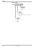
Страница 52: ...com 7 Part number NE214 AX01 Voltage supply 1 24 48 VAC 2 115 230 VAC 3 24 VDC Outputs 0 Without relay 1 Relay outputs 2 Relay and optocoupler outputs analogue output Interface 0 Without interface 1 R...

Отзывы: