OIS-P, PC3141/03 Manual
Baumer Ident
37
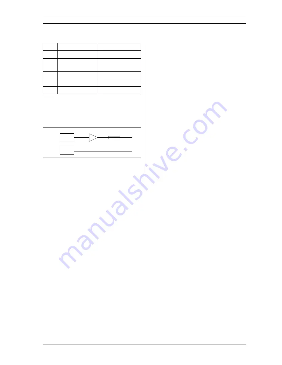
Installation and trouble-shooting tools
Points Description
Voltage value
A - B
External supply
+24 V
C - G
Antenna voltage
+18V +/- 0,5 V (with
antenna connected)
E - D
Not used
+24V +5/-2V
F -G
Antenna supply
+ 30V +/- 0,5V
H - I
Electronics supply
+5V +/- 0,1 V
Table 7.b
Figure 7.6 shows the power supply connection
circuit with the protection diode CR1 and the fuse
F1.
7.5.5 CPU Board
The Figure 7.3 shows the CPU Board in the upper
left corner.
The upper part of the figure shows the position of
the PROM and PLD which may have to be
replaced in the case of a system upgrade.
The Figure 7.3 also shows two voltage measuring
points:
E
Insulated external I/O supply: measure 24V
between IC40:9 and IC40:10
(if this voltage is connected).
E
CPU supply voltage: measure 5 V between
C50 + and C50 -
+24V
CR1 F1
4
5
0
6
9
0
+
Fig 7.6
POWER
Содержание OIS-P PC 3100 series
Страница 2: ...Page intentionally blank ...
Страница 4: ...4 Baumer Ident OIS P PC3141 03 Manual Page intentionally blank ...
Страница 6: ...6 Baumer Ident OIS P PC3141 03 Manual Page intentionally blank ...
Страница 12: ...12 Baumer Ident OIS P PC3141 03 Manual System description Page intentionally blank ...
Страница 24: ...24 Baumer Ident OIS P PC3141 03 Manual Health aspects Page intentionally blank ...
Страница 26: ...26 Baumer Ident OIS P PC3141 03 Manual Page intentionally blank Maintenance aspects ...
Страница 38: ...38 Baumer Ident OIS P PC3141 03 Manual Installation and trouble shooting tools Page intentionally blank ...
Страница 42: ...42 Baumer Ident OIS P PC3141 03 Manual Page intentionally blank ...


