background image

4

GG

MM

MM

MM

MM

CC

FF

EE

CC

HH

HH

LL

LL

LL

DD

AA

AA

AA

AA

BB

BB

BB

BB

DD

7&2

1&2

9

7&2

1&2

9

7&2

1&2

7&2

7&2

1&2

9

9

7&2

1&2

7&2

1&2

1&2

7&2

5

5

4

4

11&2

4

5

5

4

11&2

19

19

6

14

8

15

15

17&18

15

17&18

3

8

15

13

13

13

13

16

16

16

16

17&18

17&18

17&18

10

10

10

10

KK

JJ

ONLY ONE
LIFT SHOWN
FOR CLARITY

OPTIONAL

5

(8   )

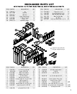
MECHANISM PARTS LIST

SEE PAGES 14-15 FOR ELECTRICAL AND HYDRAULIC PARTS

ITEM

PART NO.

DESCRIPTION

QTY.

JJ

HH

A427-0014

W102-0045

Bunk Rail Assembly, Left

H-frame Arm, Inner

2

8*

KK

A427-0015

Bunk Rail Assembly, Right

2

LL

W410-0067

Bunk Board Assembly (part of JJ, KK)

(4)

MM

NN

N/A

M621-1002

K200-0127

Base Pivot Bushing

Pivot Block

16

8

ITEM

PART NO.

DESCRIPTION

QTY.

AA

BB

CC
DD

EE

FF

GG

K200-0125
W117-0001

W105-0012

W111-0019

A431-0040
A431-0039

SEE PG. 14

Leg

Foot Pad

Side Rail

Base Crossmember

H-frame, Forward

H-frame, Aft

Hydraulic Cylinder

4

4

4
2

2

2

2

ITEM

PART NO.

DESCRIPTION

QTY.

Y356-0003

anti-seize grease packet

2

S532-1801

P pin SS

4

14

S503-0010

bunk pin SS

8

15
16

S362-0108

nut, 3/8-16 nylock thin SS

8

17

18

F730-0021

plastic cap for 2" ID sq tube

4

19

S503-0016

clevis pin, 3/4 x 3.5 SS

2

20

S503-0011

extension pin SS

0

21

22

23

24

25

S103-0705

S103-0338

S322-0006

bolt, hex head 1/4-20 x 1.75 full thread SS

bolt, hex head 1/2-13 x 1.0 SS

washer, lock 1/4 SS

4

8

8

ITEM

PART NO.

DESCRIPTION

QTY.

1

2

3
4

5
6
7

8

9

10
11

12

13

S362-0008

S313-0008

S313-0007
S322-0007

S342-0007
S503-0015
S103-0515

S503-0012

S314-0032

S103-0516

S522-0801

S520-1706

nut, 3/8-16 nylock SS

washer, flat 3/8 SS

washer, flat 5/16 SS

washer, lock 5/16 SS

nut, 5/16-18 SS

clevis pin 3/4 x 5.0 SS

bolt, hex head 3/8 - 16 x 3-1/2 SS

base pivot pin SS

washer, flat 3/4 nylon

bolt, hex head 3/8 - 16 x 3-3/4 SS

ring cotter pin 3/4 x .091 SS

cotter pin 3/16 x 2.0 SS

12

32

12
12

12

2

8

8

4

12

4

8

(8   )

(16   )

(16   )

QUANTITIES INCLUDED WITH
OPTIONAL EXTENSION ARMS

20

13

25

24

16

3

11

5

4

23

15

8

10

14

22

7

2

18

6

9

2

2

1

21

17&18

17&18

17&18

10

KK

Содержание Over-Center 2x2k

Страница 1: ...ttempting assembly or operation 04 21 L392 0097B tm Over Center Hydraulic Aluminum Lift 4 000 lbs Capacity 2 000 lbs 2 000 lbs Model 2x2k 866 GO BASTA www gobasta com ASSEMBLY INSTALLATION REPLACEMENT...

Страница 2: ...ot service the unit with the boat on the lift Use a mooring line for additional security Only use Basta Marine approved oil in lift Special biodegradable non toxic hydraulic fluid Visually inspect all...

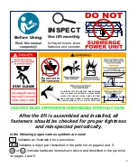
Страница 3: ...nstalled all fasteners should be checked for proper tightness and reinspected periodically INSPECT the lift monthly for frayed hoses loose fasteners and corrosion Before Using Read this manual complet...

Страница 4: ...BB DD 7 2 1 2 9 7 2 1 2 9 7 2 1 2 7 2 7 2 1 2 9 9 7 2 1 2 7 2 1 2 1 2 7 2 5 5 4 4 11 2 4 5 5 4 11 2 19 19 6 14 8 15 15 17 18 15 17 18 3 8 15 13 13 13 13 16 16 16 16 17 18 17 18 17 18 10 10 10 10 KK J...

Страница 5: ...8 16 nylock thin SS 8 17 18 F730 0021 plastic cap for 2 ID sq tube 4 19 S503 0016 clevis pin 3 4 x 3 5 SS 2 20 S503 0011 extension pin SS 0 21 22 23 24 25 S103 0705 S103 0338 S322 0006 bolt hex head...

Страница 6: ...10 QTY 4 3 8 nylon insert lock nuts 1 QTY 8 3 8 flat washers 2 QTY 4 leg P pins 15 QTY 4 1 2 x 1 0 bolts 23 A A BB DD NOTE the 3 different holes shown can be used for pin 15 to allow fine height adju...

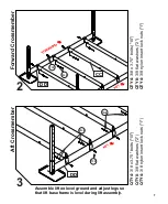
Страница 7: ...rt lock nuts 1 QTY 4 3 8 x 3 75 bolts 10 QTY 8 3 8 flat washers 2 QTY 4 3 8 nylon insert lock nuts 1 CC DD DD Forward Crossmember 2 Aft Crossmember 3 1 2 10 2 10 2 10 2 1 2 Assemble lift on level grou...

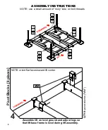
Страница 8: ...vot Blocks 8 places 4 Assemble lift on level ground and adjust legs so that lift base frame is level during lift assembly NOTE use a small amount of moly lube on bolt threads ASSEMBLY INSTRUCTIONS QTY...

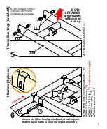
Страница 9: ...S 5 H frames 4 places 6 Assemble lift on level ground and adjust legs so that lift base frame is level during lift assembly are installed with curved side up EE NOTE no washer on this end QTY 8 THIN 3...

Страница 10: ...er with lift in down position QTY 2 3 4 x 3 5 clevis pin 21 QTY 2 3 4 x 5 clevis pin 6 QTY 4 ring type cotter pins 11 QTY 4 3 4 nylon flat washers 9 Cylinders 7 NOTE install cylinders with hose fittin...

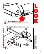
Страница 11: ...stall cylinder with hose fittings facing down Cylinders 8 port points down Optional extension arms only Inner Arms 8 places if used QTY 4 extension pins 22 QTY 4 1 4 x 1 75 bolt 24 QTY 4 1 4 lock wash...

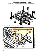
Страница 12: ...EMBLY INSTRUCTIONS 12 12 10 10 12 12 10 10 Complete Step 11 to raise lift to install screws for pins See Step 12 for details 16 16 KK JJ 16 16 Bunk Rail Assembly QTY 8 bunk pivot pins 16 SHORT AT AFT...

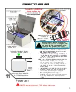
Страница 13: ...o their corresponding Quick Couplers and their terminals are tight use a wrench one inch only add fluid with lift in DOWN position Ensure each Quick Coupler is completely seated and tight with no gap...

Страница 14: ...H310 0008 Item GG on pg 4 CONTROL PANEL ASSEMBLY R815 0010 BATTERY SAFETY IS IMPORTANT Follow all battery manufacturer s warnings and safety information R812 0011 Y354 0001 Hydraulic Cylinder H412 420...

Страница 15: ...l amount of moly lube on bolt threads ASSEMBLY INSTRUCTIONS 12 12 Bunk Rail Assembly 12 QTY 4 1 4 x 1 75 bolts 24 QTY 4 1 4 lock washers 25 24 25 KK JJ raise lift to install 1 4 x 1 75 bolts 24 24 25...

Страница 16: ...nnect the hydraulic hose quick couplers in the Power Unit box Raise the lift fully and finish adjusting the legs so that the base frame is level side to side and forward to aft 15 Adjust the legs to p...

Страница 17: ...thout settling tm 3 Remove the boat Verify that the lift frame is level Re level the framework if necessary NOTE If you purchased a new water craft be sure it is within the weight capacity limits of t...

Страница 18: ...uire replacement for a considerable amount of time If yours has been contaminated or the hydraulic power unit has been replaced visit our web site at www gobasta com for detailed instructions POWER UP...

Страница 19: ...ugness and corrosion Check the hydraulic fluid and battery electrolyte levels The battery electrolyte should be slightly above the indicator ring in each cell Carefully add DISTILLED water if necessar...

Страница 20: ...active Authorized Dealer within 50 miles of the location of the Product Labor will not be provided for direct purchases from Company or when an active Authorized Dealer is not located within 50 miles...

Отзывы: