12
10
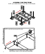
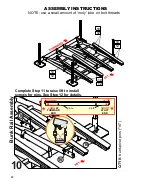
NOTE: use a small amount of 'moly' lube on bolt threads
ASSEMBLY INSTRUCTIONS
12
12
10
10
12
12
10
10
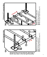
Complete Step 11 to raise lift to install
screws for pins. See Step 12 for details.
16
16
KK
JJ
16
16
B
u
n
k
R
a
il
A
s
s
e
m
b
ly
Q
T
Y
8
:
b
u
n
k
p
iv
o
t
p
in
s
("
1
6
")
13
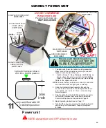
Power unit
NOTE: always turn unit OFF when not in use
11
CONNECT POWER UNIT
6.
Test the lift on dry ground using the Up/Down Switch
and the Key Fob Transmitters. Inspect the system
for leaks.
1.
The Hydraulic Power Unit will arrive fully assembled.
Make sure all the connections are snug to prevent
leaks or loss of power to the unit.
Install a Group 31 Deep Discharge AGM Battery as
shown above. Be sure to connect the Red Battery
Cable to the p ositive terminal and the Black Battery
Cable to the negative terminal.
NOTE:
Ensure battery cables are correctly connected
3.
Slide the Hydraulic Hose Assembly through the
access hole in the side of the fiberglass Enclosure
and attach the ends to their corresponding
Quick Couplers.
and their terminals are tight (use a wrench).
one
inch
only add fluid with lift
in DOWN position
Ensure each Quick Coupler is
completely seated and
tight
with
no gap at the connection joint.
Connection must be
tight
to open internal
check valve and allow fluid to flow. USE PLIERS
DO NOT SUBMERSE
Keep inside dry
4. Plug the cable from the Solar Panel into the connector
on the wiring harness that comes from the Remote
Control Unit as shown in the picture on Page 14.
NO GAP!
Prevent unauthorized use -
KEEP BOX LOCKED
hydraulic fluid level shown
with lift in DOWN position
2.
COMPLETE POWER UNIT
#
H653-0001
power
switch
POSITIVE BATTERY
CABLE (RED)
#
R711-1010
NEGATIVE BATTERY
CABLE (BLACK)
#
R711-1005
HOSE ASSEMBLIES
#
H123-0001
remote
receivers
up/down
switches
MALE QUICK COUPLER
#
H770-0002
FEMALE QUICK COUPLER
#
H770-0001
5.
Read Operating Instructions on Page 17.
SHORT
AT AFT
END
LONG
AT
FORWARD
END
plate
plate
pre-installed
bushings are


