


4
5
1
2
3
4
5
6
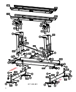
MECHANISM PARTS LIST
SEE PAGES 13 & 14 FOR ELECTRICAL AND HYDRAULIC PARTS
ITEM
PART NO.
DESCRIPTION
QTY.
1
2
3
4
5
6
7
8
9
11
S362-0008
S313-0008
S503-0013
S103-0517
S503-0012
S314-0032
S103-0516
S522-0801
nut, 3/8-16 nylock SS
washer, flat 3/8 SS
clevis pin, 3/4 x 3.5 SS hardened
bolt, hex head 3/8-16 x 4 SS
base pivot pin SS
washer, flat 3/4 nylon
bolt, hex head 3/8-16 x 3.75 SS
ring cotter pin .091 x 3/4 SS
14
28
2
2
4
2
12
2
S532-1801
P pin, SS
4
12
S503-0020
bunk pin, SS
4
13
14
15
16
F730-0021
plastic cap for 2-1/2" OD sq tube
4
17
18
S103-0705
S503-0011
S103-0338
S322-0006
S520-1706
bolt, hex head 1/4-20 x 1.75 full thread SS
bolt, hex head 1/2-13 x 1.0 SS
extension arm pin
washer, lock 1/4 SS
cotter pin 3/16 x 2.0 SS
4
4
8
8
4
ITEM
PART NO.
DESCRIPTION
QTY.
8
14
11
5
7
10
13
3
2
2
1
12
4
2
18
16
15
17
18
18
6
3
8
KK
EE
11
11
11
11
DD
DD
14
14
14
14
17
17
17
17
7&2
7&2
7&2
7&2
1&2
1&2
1&2
1&2
BB
BB
BB
BB
BB
BB
BB
BB
AA
AA
AA
AA
CC
CC
1&2
1&2
7&2
7&2
3
8
KK
7&2
7&2
1&2
GG
FF
9
9
5
5
13
HH
1&2
1&2
15&16
LL
1&2
4&2
4&2
9
5
9
5
JJ
13
2
1
S103-0503
bolt, hex head 3/8-16 x 3/4 SS
4
LL
15&16
19
L129-0001
key fob floats
2
10
Y356-0003
anti-seize grease packet
1
9
15&16
15&16
6
12
20
12
20
12
20
12
20
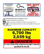
LIFT: A206-6603
20
20
S520-1604
cotter pin 5/32 x 1.5 SS
8
19
N/A
S313-0013
washer, flat 3/4 SS
8
15&16
15&16
19
19
19
19
7
1
2
2
MM
NN
MM
NN
A427-0031
MM *
ITEM
PART NO.
DESCRIPTION
QTY.
A427-0032
NN *
N/A
W410-0082
N/A
S313-0007
N/A
S322-0007
N/A
S342-0007
N/A
W114-0019
N/A
W114-0020
N/A
M621-1009
Bunk Rail Assembly, Left Rubber
Bunk Rail Assembly, Right Rubber
Bunk Board Assembly (part of MM, NN)
1*
1*
(2)
washer, flat 5/16 (part of MM, NN)
(6)
washer, lock 5/16 (part of MM, NN)
(6)
nut, 5/16-18 (part of MM, NN)
(6)
Bunk Rail Weldment, Left (part of MM)
(1)
Bunk Rail Weldment, right (part of MM)
(1)
Bunk Pivot Bushing (part of MM, NN)
(8)
A427-0024
MM
A427-0025
NN
Bunk Rail Assembly, Left Std.
Bunk Rail Assembly, Right Std.
1
1
these parts are optional and replace the std. parts
ITEM
PART NO.
DESCRIPTION
QTY.
HH
W107-0006
Stop Block, Left
1
AA
BB
CC
DD
EE
FF
GG
K200-0001
W117-0001
W105-0013
W111-0018
A431-0048
A431-0047
SEE PG. 14
Leg
Foot Pad
Side Rail
Base Crossmember
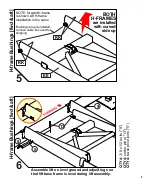
H-frame, Forward
H-frame, Aft
Hydraulic Cylinder
4
4
2
2
1
1
1
JJ
W107-0007
Stop Block, Right
1
KK
8
M621-1002
Base Pivot Bushing
4
LL
K202-0265
H-Frame arm, inner
MM
NN


