Basta Boatlifts 6.7k60 AR Скачать руководство пользователя страница 14

14

15

28

# R811-0010

Remote Control Receiver

 with Fobs

Remote Key Fobs

POWER UNIT

ASSEMBLY

#

 H603-0012

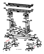
Please order replacement parts by PART NO. and DESCRIPTION

pre-wired

with wiring

harness

Hydraulic Fluid (quart)
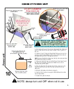
CONTROL PANEL

ASSEMBLY

#

 R815-0008

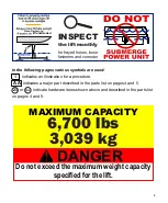
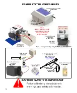
BATTERY SAFETY IS IMPORTANT

Follow all battery manufacturer’s 
warnings and safety information.

Padlock

not included

SOLAR PANEL ASSEMBLY

#

 R281-0004

ENCLOSURE

#

 C243-0003

# R812-0012

# Y354-0001

POWER SYSTEM COMPONENTS

# R283-0002

Solar Controller

Connect to Solar Panel

Connected

pre-charged with

hydraulic fluid

Hydraulic Cylinder Assembly

#H310-0001

(Item GG on pg 5)

Hose Assembly

#H123-0037

Hydraulic Fittings

#H711-0002

NOTE:

REMOVE SHIPPING PLUG IN

RESERVOIR AND REPLACE

WITH BREATHER PLUG

BEFORE START-UP

NOTE:

REMOVE SHIPPING PLUG IN

RESERVOIR AND REPLACE

WITH BREATHER PLUG

BEFORE START-UP

11

Q

T

Y

 4

1

/4 

1

.7

5

” 

b

o

lt

("

1

5

")

Q

T

Y

 4

:

 1

/4 

lo

c

w

a

s

h

e

rs 

("

1

6

")

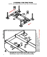
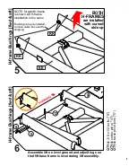
NOTE: use a small amount of 'moly' lube on bolt threads

ASSEMBLY INSTRUCTIONS

11

11

Assemble lift on level ground and adjust legs so
that lift base frame is level during lift assembly.
  

B

u

n

R

a

il 

A

s

s

e

m

b

ly 

 raise lift to install 1/4 x 1.75” bolts ("15")

15+16

15+16

NN

MM

15+16

15+16

Содержание 6.7k60 AR

Страница 1: ...60 AR REPLACEMENT PARTS INSTALLATION ASSEMBLY tm 6 700 lbs 3 039 kg Capacity Specifications subject to change 04 21 L392 0100D Over Center Hydraulic Aluminum Boat Lift 866 GoBasta www gobasta com Bast...

Страница 2: ...each use Troubleshooting FAQ Page 18 Maintenance Page 19 Never exceed lift capacity set forth in manual and on H frame of the boat lift Improper use or failure to follow this instruction can cause pr...

Страница 3: ...s are used indicates an illustration for a procedure indicates a major part described in the parts list on pages 4 and 5 or indicate hardware items shown above and described in the parts list on pages...

Страница 4: ...2 7 2 7 2 1 2 1 2 1 2 1 2 BB BB BB BB BB BB BB BB AA AA AA AA CC CC 1 2 1 2 7 2 7 2 3 8 KK 7 2 7 2 1 2 GG FF 9 9 5 5 13 HH 1 2 1 2 15 16 LL 1 2 4 2 4 2 9 5 9 5 JJ 13 LL 15 16 15 16 15 16 12 20 12 20 1...

Страница 5: ...ts 2 10 Y356 0003 anti seize grease packet 1 9 6 20 20 S520 1604 cotter pin 5 32 x 1 5 SS 8 19 N A S313 0013 washer flat 3 4 SS 8 7 1 2 2 A427 0031 MM ITEM PART NO DESCRIPTION QTY A427 0032 NN N A W41...

Страница 6: ...ame is level during lift assembly 1 7 2 NOTE use a small amount of moly lube on bolt threads ASSEMBLY INSTRUCTIONS Feet and Legs 4 places Assemble lift on level ground and adjust legs so that lift bas...

Страница 7: ...8 flat washers 2 QTY 4 3 8 nylon insert lock nuts 1 Forward Crossmember 2 3 Assemble lift on level ground and adjust legs so that lift base frame is level during lift assembly Assemble lift on level...

Страница 8: ...olts 4 NOTE use a small amount of moly lube on bolt threads ASSEMBLY INSTRUCTIONS Stop Blocks Assemble lift on level ground and adjust legs so that lift base frame is level during lift assembly note l...

Страница 9: ...ift on level ground and adjust legs so that lift base frame is level during lift assembly 5 13 9 5 H frame Bushings fwd aft KK KK BOTH H FRAMES are installed with curved side up EE NOTE forward H fram...

Страница 10: ...threads ASSEMBLY INSTRUCTIONS 7 7 10 7 18 15 16 LL QTY 4 extension pins 18 QTY 4 1 4 x 1 75 bolt 15 QTY 4 1 4 lock washer 16 Assemble lift on level ground and adjust legs so that lift base frame is le...

Страница 11: ...stic washers here 8 3 6 6 NO washers here 8 3 6 8 QTY 2 3 4 x 3 5 clevis pin 3 QTY 2 3 4 ring type cotter pin 8 QTY 2 3 4 nylon flat washers 6 Install cylinder with lift in down position Cyliner 8 8 N...

Страница 12: ...8 3 4 washers 19 The angles and directions of bunk rail assemblies MUST face the directions shown below Bolts that hold the pins will be installed in step 11 12 12 MM NN bushings are pre installed Ri...

Страница 13: ...c fluid level with lift in DOWN position breather cap REPLACE SHIPPING PLUG WITH BREATHER CAP ATTACHED TO CONTROL PANEL 1 The Hydraulic Power Unit will arrive fully assembled Make sure all the connect...

Страница 14: ...and safety information Padlock not included SOLAR PANEL ASSEMBLY R281 0004 ENCLOSURE C243 0003 R812 0012 Y354 0001 POWER SYSTEM COMPONENTS R283 0002 Solar Controller Connect to Solar Panel Connected p...

Страница 15: ...e a small amount of moly lube on bolt threads ASSEMBLY INSTRUCTIONS 11 11 Assemble lift on level ground and adjust legs so that lift base frame is level during lift assembly Bunk Rail Assembly raise l...

Страница 16: ...vel the lift Continue repeating this step until the boat lift can be raised into the full Over Center position without settling TM 3 Remove the boat Verify that the lift frame is level Re level the fr...

Страница 17: ...17 Use these diagrams to help place the lift 135 117 36 138 84 to 70 53 to 39 24 26 to 24 to 22 21...

Страница 18: ...tion has a ten second delay Failure to wait for this ten seconds can make the wait time much longer LIFT OPERATION The remote fob is non functional until it is enabled by depressing the lower right bu...

Страница 19: ...s for snugness and corrosion We STRONGLY recommend the use of a maintenence free AGM type battery In a flooded cell type battery the electrolyte should be slightly above the indicator ring in each cel...

Страница 20: ...active Authorized Dealer within 50 miles of the location of the Product Labor will not be provided for direct purchases from Company or when an active Authorized Dealer is not located within 50 miles...

Отзывы: