


RDG603A27
– Issue 6
Page 18 of 59
SECTION 4
– Installation
NOTICE:
REFER TO THE SHIRE AND ENGINE MANUALS PRIOR TO INSTALLING THE
ENGINE.
1. Ventilation
All internal combustion engines radiate heat and require cool, clean air to aid complete
combustion.
Please Ensure that adequate engine room ventilation is provided, by fitting at least two
vents of an aperture of not less than 15,000mm2 each (24in
2
).
An allowance must be made for any grills, louvres or bends placed in the
airflows and generally an increase of 25% in area is sufficient to overcome any
restriction problems.
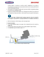
2. Engine Beds
These should be a minimum of 10mm thick, extended rearward and be welded to the
hull and forward to the bulkhead. Webs or gussets must be welded in place midway
to prevent flexing.
3. Pressurised Water Header Tank
WARNING:
SCALD HAZARD!
NEVER REMOVE THE HEADER TANK CAP IF THE ENGINE IS
HOT. STEAM AND HOT COOLANT MAY SPURT OUT AND CAUSE INJURY. TIGHTEN
THE HEADER TANK CAP SECURELY AFTER BEING REMOVED. STEAM CAN
SPURT OUT DURING ENGINE OPERATION IF THE CAP IS LOOSE.
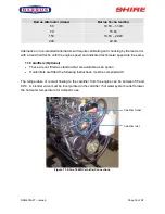
The pressurised header tank should be mounted higher than the level of the engine
and no more than 1 metre from the engine. This is to prevent cooling system air locks.
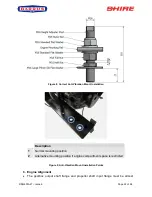
The smaller internal diameter hose tail (left side of the tank) should be connected to
the top of the engine. This is the air-bleed. The larger internal diameter hosetail (right