Barnes 4SE-EDS Series Скачать руководство пользователя страница 9

Lowest noise level indicates correct rotation.

4.) Another method that can be used if unit is installed in

tank is to close discharge line. With adequate water to
place pump under load, start pump and check 
amperage draw on all three lines. Stop pump, reverse
two leads (red, white, or black). Restart and recheck
amperage draw on the three lines. Lowest average
amperage occurs when pump is running correct
rotation. Note the noise level when unit is pumping.
Lowest noise level indicates correct rotation.

D-3) Start-Up Report:

Included at the end of this manual are two start-up report
sheets, these sheets are to be completed as applicable. Return
one copy to Barnes Pumps, Inc. and store the second in the
control panel or with the pump manual if no control panel is
used. It is important to record this data at initial start-up since
it will be useful to refer to should servicing the pump be required
in the future.

D-3.1) Identification Plate:

Record the numbers from the pump’s identification plate on
both START-UP REPORTS provided at the end of the manual
for future reference.

D-3.2) Insulation Test:

Before the pump is put into service, an insulation (megger) test
should be performed on the motor. The resistance values
(ohms) as well as the voltage (volts) and current (amps) should
be recorded on the start-up report.

D-3.3) Pump-Down Test:

After the pump has been properly wired and lowered into the
basin, sump or lift station, it is advisable to check the system
by filling with liquid and allowing the pump to operate through
its pumping cycle. The time needed to empty the system, or
pump-down time along with the volume of water, should be
recorded on the start-up report.

SECTION E: PREVENTIVE MAINTENANCE

The sealed motor is oil filled and is lubricated for life, no internal
lubrication or other maintenance is required, if there is evidence
of internal problems, the unit should be taken to an authorized
service station. 
However as with any mechanical piece of equipment a
preventive maintenance program is recommended and
suggested to include the following checks:

1) Inspect impeller and body for excessive build-up or

clogging and repair as required per section F-5.

2) Inspect seal for wear or leakage and repair as

required per section F-6.

SECTION F: SERVICE AND REPAIR

NOTE:

 All item numbers in ( ) refer to Figures 19 & 20 for EL

Models and 21 & 22 for EDS Models.

F-1) Checking Oil:

To check oil or before removing seal or disassembling motor
section drain the oil by removing either pipe plug (11) in switch
end bell (42) or drive end bell (46). Catch oil in a clean
container. Check the oil for water or other contaminants, a milky
appearance indicates water has emulsified with the oil.

F-2) Testing Oil:
1.

Check oil for water contamination using an oil tester 
with a range to 30 Kilovolts breakdown.

2.

If oil is found to be clean and uncontaminated (measure
above 15 KV. breakdown), refill the motor housing 
as per section F-4.

3.

If oil is found to be dirty or water contaminated 
(or measures below 15 KV. breakdown), the the pump
must be carefully inspected for leaks before refilling with
oil. To locate the leak, perform a test as per section F-3. 
After leak is repaired, refill with new oil as per 
section F-4.

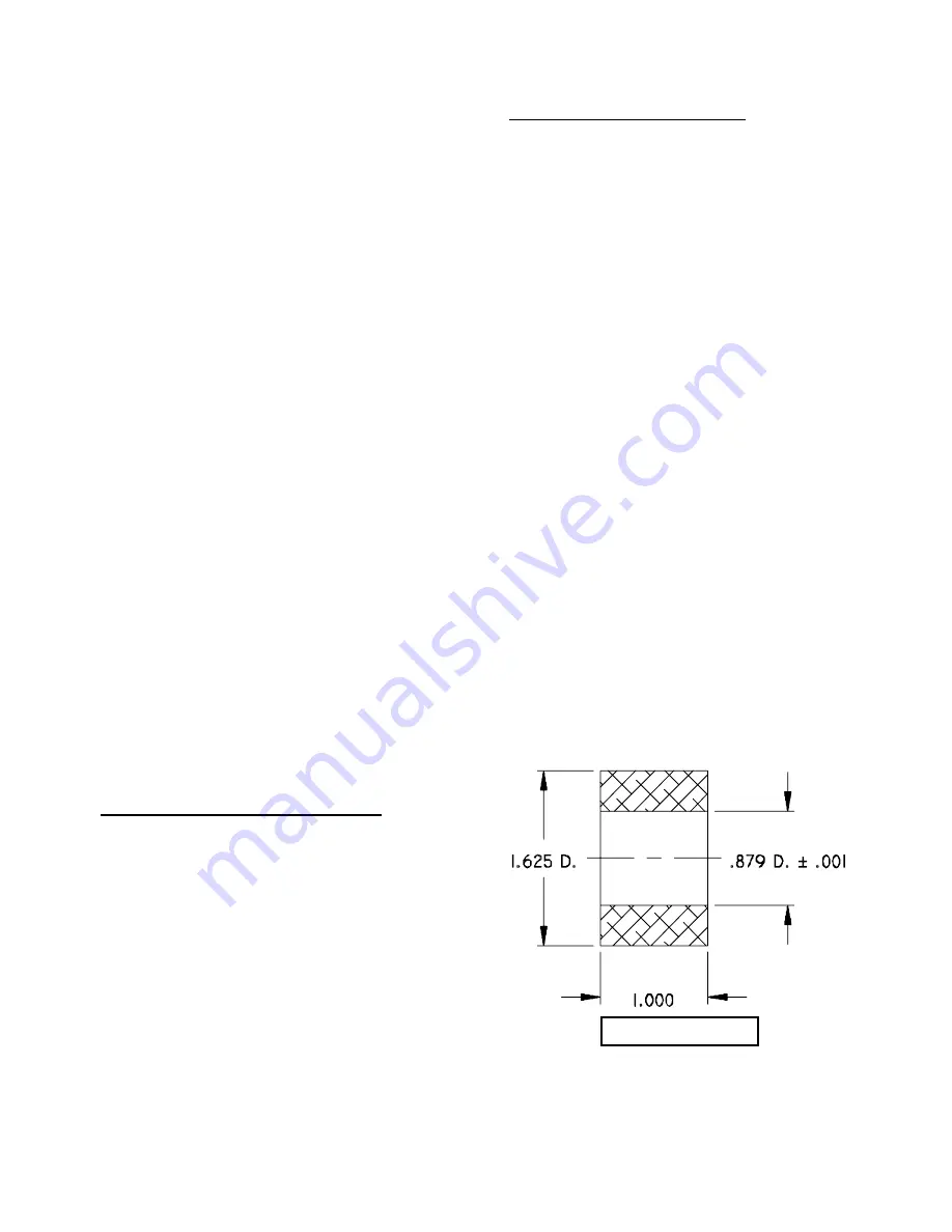
F-3.1) Leak Checking - Single Seal:

When leak checking units, seal retainer (see Figure 2) should
be used in place of impeller and top cover (20) must be
removed. Push motor diaphragm (40) down into cavity. Place
a plug with no burrs or sharp edges (see Figure 4) in recess
formed by diaphragm. Hold diaphragm plug in place with
diaphragm clamp (see Figure 5) fastened to switch end bell.
Remove pipe plug (11) from either switch end bell (42) or drive
end bell (46). Apply 8 to 10 PSI air pressure to inside of motor
housing. Submerge motor, any bubbling indicates leakage. In
any case where leakage occurs, changes must be made to
correct the problem. After removing motor from water, drain
and dry all water from top section of switch end bell (42).

Fig. 2 - Single Seal

9

Содержание 4SE-EDS Series

Страница 1: ...product changes may occur As such Crane Pumps Systems Inc reserves the right to change product without prior written notification SERIES 4SE EL 1 5 6 7HP 1750 RPM SERIES 4SE EDS 1 5 6 7HP 1750 RPM BA...

Страница 2: ...CROSS SECTION Fig 21 22 4SE EDS EXPLODED VIEW Fig 22 23 4SE EDS PARTS LIST 24 25 4SE EDS LEAK SENSOR PARTS LIST 26 4SE EDS LEAK SENSOR EXPLODED VIEW Fig 23 27 START UP REPORT WARRANTY INFORMATION WARR...

Страница 3: ...arge openings DO NOT insert fingers in pump with power connected Always wear eye protection when working on pumps Make sure lifting handles are securely fastened each time before lifting DO NOT operat...

Страница 4: ...Phase NEMA B Three Phase Torque Curve Completely Oil Filled Squirrel Cage Induction Insulation Class A SINGLE PHASE Dual Voltage 200 230 Includes Overload Protection In Motor 1 5 2 2HP Capacitor Start...

Страница 5: ...e Completely Oil Filled Squirrel Cage Induction Insulation Class A SINGLE PHASE Dual Voltage 200 230 Includes Overload Protection In Motor 1 5 2 2HP Capacitor Start 2 7 4 5HP Capacitor Start Capacitor...

Страница 6: ...ly If it is required that the pump be installed and tested before the long term storage begins such installation will be allowed provided 1 The pump is not installed under water for more than one 1 mo...

Страница 7: ...or cools to a safe temperature In the event of an overload the source of this condition should be determined and rectified immediately DO NOT LET THE PUMP CYCLE OR RUN IF AN OVERLOAD CONDITION OCCURS...

Страница 8: ...Resistance 5 Start wires Black White Main wires Black Red Pump rated for operation at 10 Voltage at Motor MODEL NO A DIM HP VOLT PH NEMA START CODE FULL LOAD AMPS LOCKED ROTOR AMPS CORD SIZE CORD TYP...

Страница 9: ...hould be taken to an authorized service station However as with any mechanical piece of equipment a preventive maintenance program is recommended and suggested to include the following checks 1 Inspec...

Страница 10: ...rated in cooler temperatures COOLING OIL Dielectric TABLE 1 SUPPLIER GRADE BP Enerpar SE100 CONOCO Pale Paraffin 22 MOBIL D T E Oil Light G G OIL Circulating 22 Imperial Oil Voltesso 35 Shell Canada T...

Страница 11: ...Fig 4 DIAPHRAGM PLUG Material 2 000 Dia Aluminum Fig 5 DIAPHRAGM CLAMP Material 750W x 375Thk Steel Fig 6 OIL FILLING 11...

Страница 12: ...e stationary member is in straight Lightly oil shaft and inner surface of bellows on rotating member With lapped surface of rotating member facing inward toward stationary member slide rotating member...

Страница 13: ...with hole in drive and bell Press housing in place and temporarily install two mounting bolts 67 Place several drops of oil inside of bellows of rotating member 13C and spread it over bellows Coat se...

Страница 14: ...Y PRESSING ON INNER RACE Support rotor assembly on ring see Figure 13 when installing top bearing so that the pressing force is not transmitted through balls of drive end bearing Place Tetraseal 43 on...

Страница 15: ...Fig 15 SINGLE PHASE 1 5HP 2 2HP Fig 16 SINGLE PHASE 2 7HP 4 5HP Fig 17 THREE PHASE 15...

Страница 16: ...cord 83 to each electrode with screws at top of electrode holder 90 See Figure 18 After the leak sensor has been reassembled with all screws and threaded hardware thoroughly tightened it must be check...

Страница 17: ...lean impeller cavity and inlet of any obstruction 9 Loosen union slightly to allow trappedair to escape Verify that turn off level of switch is set so that impeller cavity is always flooded Clean vent...

Страница 18: ...Fig 19 SERIES 4SE EL 18...

Страница 19: ...Fig 20 SERIES 4SE EL 19...

Страница 20: ...2 Pipe Plug Hex Hd 1 8 Brass 017363 13 1 Shaft Seal C CE B 4023 14 8 Hex Hd Screw 1 4 20 x 1 00 Lg Stainless 1 7 1 15 16 Lock Washer 1 4 Stainless 20 13 1 16 2 RdHd Screw 10 32 x 375 Lg Stainless 2 8...

Страница 21: ...460 3PH N4019 03 2 7HP 230 1PH N4019 09 2 7HP 230 460 3PH N4019 04 4 5HP 230 1PH N4019 10 4 5HP 230 460 3PH N4019 05 6 7HP 230 460 3PH N4019 11 48 1 Ball Bearing 039734 49 1 Ball Bearing 625 00719 50...

Страница 22: ...SERIES 4SE EDS Fig 21 22...

Страница 23: ...SERIES 4SE EDS Fig 22 23...

Страница 24: ...Plug Hex Hd 1 8 Brass 017363 13 1 Dbl Mech Shaft Seal C CE B 007 00500 13A 1 Retainer 13B 1 Spring 13C 1 Seal Face 13D 1 Seal Seat 14 8 Hex Hd Screw 1 4 20 x 1 00 Lg Stainless 1 7 1 15 18 Lock Washer...

Страница 25: ...ng Ring 625 00266 51 1 Shell 1 5 2 2HP 2 7HP 3PH 4005 01 2 7HP 1PH 4 5HP 6 7HP 4005 02 52 1 Stator 1 5HP 115V 1PH 625 00755 1 5HP 208 230 1PH 625 00753 1 5HP 208 230 3PH 625 00748 1 5HP 460 3PH 625 00...

Страница 26: ...84 1 Thread Protector 4651 85 1 Packing Nut 3 4 16 4697 3 86 2 Flat Washer 007 00301 87 1 Grommet 007 00302 88 6 RdHd Screw 8 32 x 625 Lg Stainless 9 65 1 89 1 Top Cover 4690 102 90 1 Electrode Holde...

Страница 27: ...SERIES 4SE EDS Fig 23 27...

Страница 28: ...eld performance Any additional guarantees in the nature of performance specifications must be in writing and such writing must be signed by our authorized representative Due to inaccuracies in field t...

Страница 29: ...ottom Does Impeller Turn Freely By Hand YES NO Condition Of Equipment GOOD FAIR POOR Condition Of Cable Jacket GOOD FAIR POOR Resistance of Cable Jacket GOOD FAIR POOR Resistance of Cable and Pump Mot...

Страница 30: ...Pump Off L1 L2 L2 L3 L3 L1 Voltage supply at panel line connection Pump On L1 L2 L2 L3 L3 L1 Amperage Load connection Pump On L1 L2 L3 FINAL CHECK Is pump seated on discharge properly Check for leaks...

Страница 31: ...Systems Inc Warranty Service Group IMPORTANT If you have a claim under the provision of the warranty contact your local Crane Pumps Systems Inc Distributor RETURNED GOODS RETURN OF MERCHANDISE REQUIRE...

Страница 32: ...CRANE PUMPS SYSTEMS INC WARRANTY SERVICE GROUP 420 THIRD STREET P O BOX 603 PIQUA OHIO 45356 0603 U S A PLACE STAMP HERE FOLD HERE AND TAPE DO NOT STAPLE...

Отзывы: