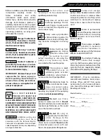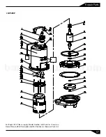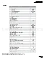
To reassemble, clean the threads with
thread locking compound cleaner.
Apply removable Loctite® 242 or
equivalent to shaft threads. Screw
impeller onto the shaft hand tight
while using a screwdriver in the slot
at the end of the shaft to hold it
stationary. Rotate impeller to check
for binding. Install U-cup by applying
adhesive to bore of volute. Be sure
not to get adhesive on inside
diameter of U-cup.
Position lock washer on cap screw
and screw into volute. Torque to 100
in/lbs. Check for free rotation of
impeller.
Shaft Seal:
To examine or replace shaft seal,
disassemble volute and impeller as
stated. Remove retaining ring, spring
and rotating member from shaft.
Inspect seal for signs of uneven wear
pattern on stationary members, chips
and scratches on either seal face.
DO
NOT interchange seal components,
replace the entire shaft seal
. If
replacing seal, remove stationary by
prying out with lat screwdrive .
f
r
Motor, Capacitor and Bearings:
Remove volute and impeller as
previously stated and drain oil from
housing. Remove shaft seal. Position
unit upright, using blocks to avoid
resting unit on shaft. Unscrew cable
cap screws and remove compression
flange and power cord. Remove snap
ring with a flat head screwdriver.
Nothing should come in contact with
the seal face except the seal tool. Be
sure the stationary is in straight.
Lightly oil
(Do not use grease)
shaft
and inner surface of bellows. Slide
rotating member onto stationary
using a seal tool. Place spring and
retaining ring onto rotating member.
Assemble impeller and volute as
described.
Place stator over rotor, lining up
motor bolts with holes in seal plate.
Place spring washer on bearing and
cover onto rotor/stator assembly.
Position capacitor so that it will lay on
the opposite side of the cable entry
boss of the housing. Install bracket
and reconnect capacitor leads.
Torque motor bolts to in/lbs. Set
square ring in grove on seal plate.
Slide rotor/shaft with bearings and
into seal plate until bearing seats into
seal plate. Install snap ring into seal
plate.
Remove cap screws from seal plate
and lift housing from seal plate.
Remove square ring, replace if cut or
damaged. Disconnect capacitor leads
from capacitor. Remove motor bolts,
lift cover, body and stator assembly
from seal plate. Remove snap ring to
remove rotor assembly. Remove
bearings and with a wheel puller.
Handle seal parts with
extreme care. DO NOT
damage lapped surfaces.
06
Service
Position gasket on volute flange and
position impeller and motor housing
assembly on volute.
CAUTION
Be sure the inside lip of
the U-cup is not pushed out of place
when assembling volute to rest of the
pump.
To reassemble, clean seal cavity in
seal plate and oil. Press seal’s
stationary member firmly into seal
plate, use a seal tool or pipe.
Pull the terminal block out of the
housing using a T-bolt or a pair of
pliers and a .25-20 screw in the
threads of the terminal block. Leave
slack on the motor leads connected
underneath. Use needle nose pliers
to pull each female connector off of
the pins on the underside of the
terminal block. The voltage should be
noted.
Check motor capacitor with an Ohm
meter by first grounding the
capacitor by placing a screwdriver
across both terminals and then
removing screwdriver. Connect Ohm
meter (set on high scale) to terminals.
If needle moves to infinity (∞) then
drifts back, the capacitor is good.
If needle does not move or moves to
infinity (∞) and does not drift back,
replace capacitor. Inspect motor
winding for shorts and check
resistance values. Check rotor for
wear. If rotor or the stator windings
are defective, the complete motor
must be replaced.
Lower housing down onto seal plate
while aligning holes and stringing
motor leads through the cord entry
bore. Place cap screws through seal
plate into housing and torque to 60
in/lbs. Reconnect motor leads to the
underside of the terminal block.
Place o-ring into groove in terminal
block and lubricate with dielectric oil.
Press the terminal block into the
housing so it seats completely below
the snap ring groove. Place snap ring
into groove in cord entry bore of
housing.
barmesapumps.com
Power Cable Connection:
Check power cord for cracks or
damage and replace if required. Refill
the cooling oil. Insert female end of
cord plug into housing bore aligning
timing markwith hole in terminal
block. Compress cord plug with
compression flange by tightening
cap screws with lock washers into the
housing. Torque to 132 in/lbs.


