IMPORTANT! -
The overload will then
automatically reset and start the
pump up after the motor cools to a
safe temperature. In the event of an
o
verload, the source of this condition
should be determined and corrected
immediately.
Three Phase -
The Normally Closed
(N/C) thermal sensor is embedded in
the motor windings and will detect
excessive heat in the event an
overload condition occurs. The
thermal sensor will trip when the
windings become too hot and will
automatically reset when the pump
motor cools to a safe temperature. It
is recommended that the thermal
sensor be connected in series to an
alarm device to alert the operator of
an overload condition, and/or the
motor starter coil to stop the pump.
In the event of an overload, the
source of this condition should be
determined and repaired.
These situations ma
a false
y induce
signal in the moisture etecting
d
circuit. If none of the above test
prove conclusive, the pump(s) should
be pulled and the source of the
failure repaired.
IF A MOISTURE
DETECT
HAS
OCCURRED
MAINTENANCE
SHOULD
BE
PERFORMED
AS
SOON
AS
POSSIBLE!
If current through the temperature
sensor exceeds the values listed, an
intermediate control circuit relay
must be used to reduce the current
or the sensor will not work properly.
TEMPERATURE SENSOR ELECTRICAL
RATINGS
Volts
Continuous
Amperes
Inrush
Amperes
110-120
3.00
30.0
220-240
1.50
15.0
440-480
0.75
7.5
600
6.0
0.60
Wire Size:
If longer power cable is required
c
a qualified electrician for
onsult
proper wire size.
DO NOT ALLOW THE
PUMP TO CYCLE OR RUN IF AN
OVERLOAD CONDITION OCCURS.
WARNING
Pre-Operation
1.
Check Voltage and Phase -
Compare the voltage and phase
information stamped on the pump
name plate.
2.
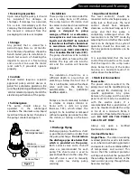
Check Pump Rotation -
Improper
motor rotation can result in poor
pump performance and can damage
the motor and/or pump. Check
rotation on three phase units by
momentarily applying power and
observe the "kickback".
Kickback should always be in a
counter-clockwise
direction
as
viewed from motor end or opposite
to impeller rotation. Impeller rotation
is counter-clockwise as viewed from
bottom of pump.
3.
Name Plate -
Record the
information from the pump name
plate to drawing in front of manual
for future reference.
4.
Insulation Test -
An insulation
(megger) test should be performed
on the motor. Before the pump is put
into service. The resistance values
(ohms) as well as the voltage (volts)
and current (amps) should be
recorded.
5.
Pump-Down Test -
Be sure pump
has been properly wired, lowered
into the basin, sump or lift station,
check the system by filling with liquid
and allowing the pump to operate
through its pumping cycle. The time
needed to empty the system, or
pump-down time along with the
volume of water, should be recorded.
04
Installation & Service
DO NOT ALLOW THE
PUMP TO CYCLE OR RUN IF AN
OVERLOAD CONDITION OCCURS.
WARNING
Moisture Sensors -
A normally open
(N/O) sensor rated of 1 watt @330K
ohms, 500 volt, is installed in the
p
ump seal chamber which will detect
any
moisture
present.
It
is
r
ecommended that this detector be
wired in series to an alarm device or
motor starter coil to alert the
operator that a moisture detect has
occurred. In the event of a moisture
detect, check the individual moisture
sensor probe leads for continuity, (∞
resistance = no moisture) and the
junction
ox/control
box
for
b
moisture content.
No lubrication or maintenance is
required. Perform the following
checks when pump is removed from
operation
or
when
pump
performance deteriorates:
Maintenance
barmesapumps.com


