background image

Manual

2100-489

Page

21 of 26

PRESSURE SERVICE PORTS

High and low pressure service ports are installed on all
units so that the system operating pressures can be
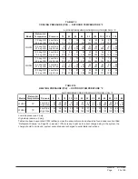
observed.  Pressure tables can be found on Page 25
covering all models.  It is imperative to match the
correct pressure table to the unit by model number.

DEFROST CYCLE

The defrost cycle is controlled by temperature and time
on the solid state heat pump control.  See Figure 16.

When the outdoor temperature is in the lower 40°F
temperature range or colder, the outdoor coil
temperature is 32°F or below.  This coil temperature is
sensed by the coil temperature sensor mounted near the
bottom of the outdoor coil.  Once coil temperature
reaches 30°F or below, the coil temperature sensor sends
a signal to the control logic of the heat pump control and
the defrost timer will start.

After 60 minutes at 30°F or below, the heat pump
control will place the system in the defrost mode.

During the defrost mode, the refrigerant cycle switches
back to the cooling cycle, the outdoor motor stops,
electric heaters are energized, and hot gas passing
through the outdoor coil melts any accumulated frost.
When the temperature rises to approximately 57°F, the
coil temperature sensor will send a signal to the heat
pump control, which will return the system to heating
operations automatically.

If some abnormal or temporary condition such as a high
wind causes the heat pump to have a prolonged defrost
cycle, the heat pump control will restore the system to
heating operation automatically after 10 minutes.

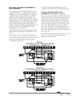
The heat pump defrost control board has an option of 30,
60 or 90-minute setting.  All models are shipped from
the factory on the 60-minute pin.  If special

circumstances require a change to another time, remove
the wire from the 60 minute terminal and reconnect to
the desired terminal.  The manufacturer’s
recommendation is for 60 minute defrost cycles.  Refer
to Figure 16.

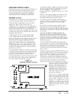
There is a cycle speed up jumper on the control.  This
can be used to reduce the time between defrost cycle
operation without waiting for time to elapse.

Use a small screwdriver or other metallic object, or
another 1/4 inch QC, to short between the 

SPEEDUP

terminals to accelerate the HPC timer and initiate
defrost.

Be careful not to touch any other terminals with the
instrument used to short the 

SPEEDUP

 terminals.  It

may take up to 10 seconds with the 

SPEEDUP

 terminals

shorted for  the speedup to be completed and the defrost
cycle to start.

As soon as the defrost cycle kicks in remove the
shorting instrument from the SPEEDUP terminals.

Otherwise the timing will remain accelerated and run
through the 1-minute minimum defrost length sequence
in a matter of seconds and will automatically terminate
the defrost sequence.

There is an initiate defrost jumper (sen jump) on the
control that can be used at any outdoor ambient during
the heating cycle to simulate a 0° coil temperature.  This
can be used to check defrost operation of the unit
without waiting for the outdoor ambient to fall into the
defrost region.

By placing a jumper across the 

SEN JMP

 terminals (a 1/4

inch QC terminal works best) the defrost sensor mounted
on the outdoor coil is shunted out and will activate the
timing circuit.  This permits the defrost cycle to be
checked out in warmer weather conditions without the
outdoor temperature having to fall into the defrost region.

In order to terminate the defrost test the 

SEN JMP

jumper must be removed.  If left in place too long the

compressor could stop due to the high
pressure control opening because of
high pressure condition created by
operating in the cooling mode with
outdoor fan off.  Pressure will rise
fairly fast as there is likely no actual
frost on the outdoor coil in this
artificial test condition.

There is also a 5-minute compressor
time delay function built into the HPC.
This is to protect the compressor from
short cycling conditions.  In some
instances it is helpful to the service
technician to override or speed up this
timing period, and shorting out the

SPEEDUP

 terminals for a few seconds

can do this.

FIGURE  16

DEFROST CONTROL BOARD

Содержание WH303

Страница 1: ...els WH303 WH363 WALL MOUNTED PACKAGED HEAT PUMP INSTALLATION INSTRUCTIONS Manual No 2100 489 Supersedes NEW File Volume III Tab 17 Date 01 18 08 Bard Manufacturing Company Inc Bryan Ohio 43506 Since 1...

Страница 2: ...6 Figure 2 Fresh Air Damper Assembly 8 Figure 3 Mounting Instructions 10 Figure 4 Electric Heat Clearance 11 Figure 5 Attaching Top Outlet to Unit 12 Figure 6 Top Outlet Model Mounted 12 Figure 7 Wall...

Страница 3: ...er and Summer Air Conditioning Duct Design for Residential ACCA Manual D Winter and Summer Air Conditioning and Equipment Selection FOR MORE INFORMATION CONTACT THESE PUBLISHERS ACCA Air Conditioning...

Страница 4: ...supply and return ducts These instructions explain the recommended method to install the air cooled self contained unit and the electrical wiring connections to the unit These instructions and any in...

Страница 5: ...U T B A U T B A U T B A U T B A U T B 5 8 0 2 5 6 0 7 1 1 8 1 0 0 8 2 1 8 0 2 5 6 0 7 1 1 8 1 0 0 8 2 1 0 1 6 1 4 0 3 1 4 3 2 6 3 0 0 6 5 2 6 1 4 0 3 1 4 3 2 6 3 0 0 6 5 2 5 1 5 2 6 0 0 2 1 5 1 4 5 0...

Страница 6: ...BASIC UNIT NOMINAL l e d o M h t d i W W h t p e D D t h g i e H H y l p p u S n r u t e R E F G I J K L M N O P Q R S T A B C B 0 3 H W 6 3 H W 0 0 2 8 3 5 2 1 7 1 3 6 5 0 7 8 8 7 8 8 7 2 8 8 3 1 8...

Страница 7: ...8 8 3 5 3 5 6 2 2 5 0 6 0 6 0 3 0 6 6 6 0 1 6 0 1 0 1 0 1 0 1 Z 0 B 0 0 B 3 6 3 H W 6 0 B 3 9 0 B 5 5 1 B 3 8 0 2 0 3 2 1 1 1 1 0 2 8 3 7 4 0 5 5 2 0 4 0 5 0 5 0 1 8 8 8 0 1 0 1 0 1 0 1 Z 0 C 0 0 C 3...

Страница 8: ...the noise transmission to a minimum A 1 4 inch clearance to combustible material for the first three 3 feet of duct attached to the outlet air frame is required See Wall Mounting Instructions and Fig...

Страница 9: ...pped secured to the back of the unit on the right side Attached to unit front right of supply flange for shipping 6 Position unit in opening and secure with 5 16 lag bolts use 7 8 inch diameter flat w...

Страница 10: ...Manual 2100 489 Page 10 of 26 FIGURE 3 MOUNTING INSTRUCTIONS...

Страница 11: ...AT CLEARANCE WARNING A minimum of 1 4 clearance must be maintained between the supply air duct and combustible materials This is required for the fist three 3 feet of ducting It is important to insure...

Страница 12: ...Manual 2100 489 Page 12 of 26 FIGURE 5 ATTACHING TOP OUTLET AIRFRAMES TO UNIT FIGURE 6 UNIT WITH TOP OUTLET MOUNTED UNDER OVERHANG...

Страница 13: ...0 489 Page 13 of 26 FIGURE 7 WALL MOUNTING INSTRUCTIONS FIGURE 8 WALL MOUNTING INSTRUCTIONS SEE FIGURE 3 MOUNTING INSTRUCTIONS SEE UNIT DIMENSIONS FIGURE 1 FOR ACTUAL DIMENSIONS SEE FIGURE 1 FOR DUCT...

Страница 14: ...Manual 2100 489 Page 14 of 26 FIGURE 9 COMMON WALL MOUNTING INSTALLATIONS...

Страница 15: ...TAGE WIRING 230 208V 1 phase and 3 phase equipment dual primary voltage transformers All equipment leaves the factory wired on 240V tap For 208V operation reconnect from 240V to 208V tap The acceptabl...

Страница 16: ...W VOLTAGE WIRING TABLE 5 THERMOSTAT WIRE SIZE r e m r o f s n a r T A V A L F e g u a G e r i W m u m i x a M e c n a t s i D t e e F n I 5 5 3 2 e g u a g 0 2 e g u a g 8 1 e g u a g 6 1 e g u a g 4...

Страница 17: ...oor temperature for heat pump option Inhibit electric heat operation for heat pumps above selected outdoor temperature FIGURE 11 COMPRESSOR CUTOFF THERMOSTAT WIRING 4 10KW 1 PH 6 9KW 3 PH Thus not req...

Страница 18: ...thermostat This is done to maximize efficiency by utilizing the heat pump to bring the conditioned space temperature up rather than cycling on the electric heat due a second stage call for heat from t...

Страница 19: ...2 5 H T t a e h e g a t s 2 l o o c e g a t s 2 e l b a m m a r g o r P n o N c i n o r t c e l E r e v o e g n a h c l a u n a M r o o t u A 0 6 0 3 0 4 8 5 4 4 0 2 1 1 t a e h e g a t s 3 l o o c e...

Страница 20: ...d outdoor motor The G indoor motor circuit is automatically completed on any call for cooling operation or can be energized by manual fan switch on subbase for constant air circulation START UP HEATIN...

Страница 21: ...mper on the control This can be used to reduce the time between defrost cycle operation without waiting for time to elapse Use a small screwdriver or other metallic object or another 1 4 inch QC to sh...

Страница 22: ...c p m u p t a e h n o y a l e r n a f s s o r c a k c e h C l o r t n o c p m u p t a e h e c a l p e R e v i t c e f e d r o t o M r o t o m e c a l p e R g n i d n i w r o t o m d e t r o h s r o n...

Страница 23: ...0 0 4 0 1 4 0 2 4 0 3 4 0 4 4 0 5 4 0 6 4 0 7 4 0 8 4 0 9 4 0 0 5 5 8 9 6 5 4 8 2 5 5 0 4 6 3 5 1 5 0 2 5 4 1 5 0 5 8 2 0 9 4 0 9 5 7 4 0 0 2 6 4 5 5 8 4 4 4 5 5 3 4 5 9 2 2 4 7 7 0 1 4 8 9 8 9 3 7 5...

Страница 24: ...filter REMOVAL OF FAN SHROUD 1 Disconnect all power to unit 2 Remove the screws holding both grilles one on each side of unit and remove grilles 3 Remove screws holding fan shroud to condenser and bot...

Страница 25: ...2 7 8 4 3 2 8 8 2 5 2 0 9 9 6 2 2 9 9 8 2 4 9 8 0 3 6 9 8 2 3 9 9 0 5 3 3 6 3 H W B D g e d 5 7 B W g e d 2 6 e d i S w o L e d i S h g i H 9 6 4 0 2 1 7 8 1 2 3 7 4 3 2 5 7 0 5 2 7 7 4 6 2 8 7 0 8 2...

Страница 26: ...t a l P f f O k n a l B X X X X X X 3 D A F B r e p m a D r i A h s e r F c i r t e m o r a B X X X X X X 3 D A F M r e p m a D r i A h s e r F d e z i r o t o M X X X X X X 3 V R C t s u a h x E h t...

Отзывы: