Manual 2100-670I
Page
8 of 47
4. Press UP or DOWN key on desired value until value
displays correctly.
5. Press ENTER key to save and scroll to next
parameter.
6. Press ESCAPE key until Main Menu screen is
displayed.
Information
The information screens are used as a quick reference
to show unit operational information such as staging,
A/C circuit measurements, last 24 hour run times,
component lifetime hours and software versioning.
Staging Information
Staging information is used to show any unit operation
that should be taking place. The look of the staging
display depends on if the unit is communicating with a
supervisory controller.
Stand Alone Demand and Staging
If the unit is operating in a stand alone mode, the
title will display as
Unit Demand
(see Figure 5). This
signifies that the local unit has control of the unit
heating and cooling stages.
The Quick Menu is accessible from the main Status
screen. Setpoints, Information and Alarm Log are
available through the Quick Menu. Pressing the UP or
DOWN keys while on the main Status screen will change
the Quick Menu icon displayed (see Figure 3). Press the
ENTER key when the desired icon is displayed.
FIGURE 3
Quick Menu Icons
Alarm Log
Information
Setpoints
NOTE:
Screenshots shown in this manual reflect
default settings (when applicable).
Quick Menu
Setpoints
From this screen, the local unit heating and cooling
setpoints, used for stand alone operation only, can be
changed.
Once the supervisory controller is connected, cooling
and heating setpoints will be communicated and local
cooling and heating setpoints will be replaced with the
communicated cooling and heating setpoints.
If at any time the wall-mount unit(s) loses
communication with the LV1000 controller, the
wall-mount unit(s) will go into stand alone mode and
operate using the last communicated setpoints.
To verify or change the wall-mount unit cooling and
heating setpoints in stand alone mode:
1. Connect the TEC-EYE diagnostic tool to the control
board located in the unit.
2. From the Status screen, press UP or DOWN key
until Quick Menu displays Setpoints icon. Press
ENTER key.
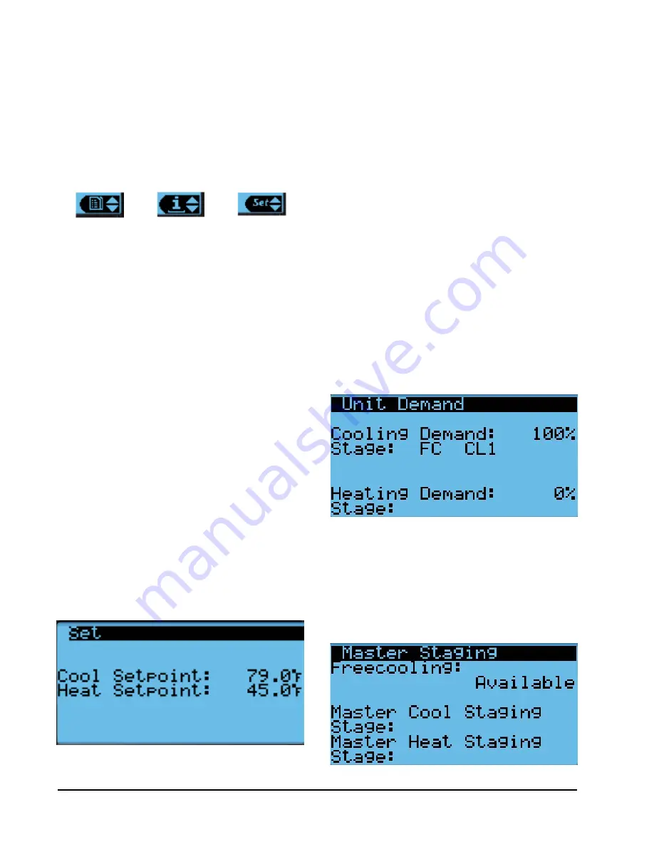
3. Press ENTER key to scroll to the selected choice
(see Figure 4).
FIGURE 5
Stand Alone Demand and Staging
Master Staging
If the unit is communicating with a supervisory
controller, the title will display as
Master Staging
(see
Figure 6). This signifies that the supervisory controller
has control of the unit heating and cooling stages.
FIGURE 6
Master Staging
FIGURE 4
Cool and Heat Setpoints


