background image

7. Advanced

Image 7-140

The common color values are automatically calculated based on the measured values of both projectors and these calculated
values are put in the

Desired values

of both projectors. Both projectors will now operate within the same color gamut.

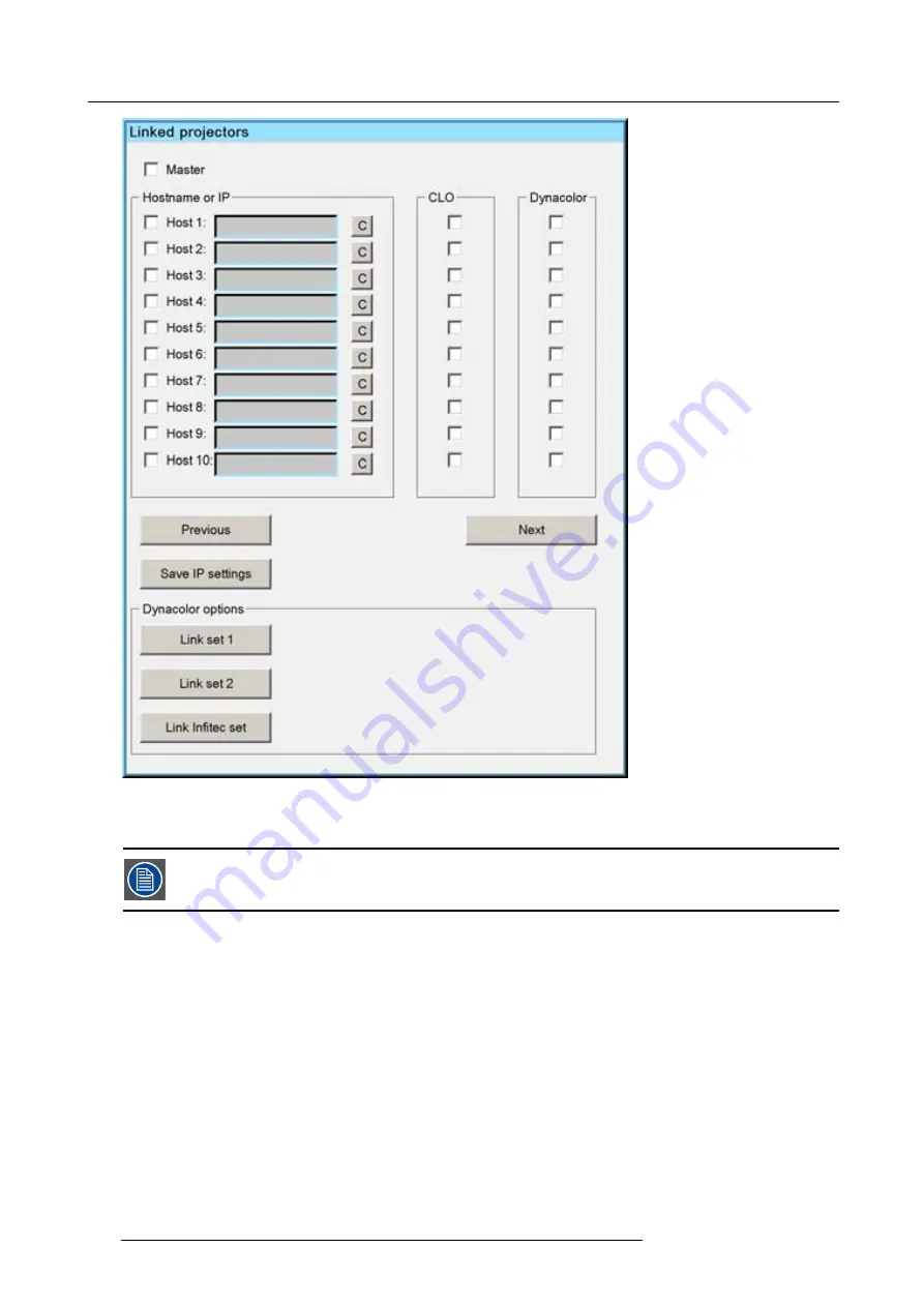
Link Set can only be performed if the linked CLO has been enabled, see

Linked Projectors

.

7.7.6.4.4

In

fi

tec common color values

Manually : Calculating the In

fi

tec common color values

1. Calculate the common values and

fi

ll them in the

Desired values

of both projectors.

Both projectors will now operate within the same color gamut.

Automatically : Link Set

1. Start up the

Linked Projector

menu of the Master projector

2. In the Linked Projector menu press the

Link In

fi

tec Set

button

The common color values are automatically calculated based on the measured values of both projectors and these calculated
values are put in the

Desired values

of both projectors. Both projectors will now operate within the same color gamut.

120

R59770247 SIM 5H 04/06/2008

Содержание SIM 5H

Страница 1: ...Sim 5H Owner Manual R9040390 R59770247 00 04 06 2008...

Страница 2: ...Barco nv Avionics and Simulation Division Noordlaan 5 B 8520 Kuurne Phone 32 56 36 82 11 Fax 32 56 36 84 86 E mail info barco com Visit us at the web www barco com Printed in Belgium...

Страница 3: ...tware on the date of commissioning at latest 30 days after the transfer of risks In the event of justified notice of complaint Barco can repair the fault or provide a replacement at its own discretion...

Страница 4: ......

Страница 5: ...ss only if necessary 33 5 3 Setting up the orientation 34 5 4 Adjusting the lens 35 5 5 Setup the baud rate for serial communication 37 5 6 Preferences 37 5 6 1 Preferences 37 5 6 1 1 Language setting...

Страница 6: ...7 6 General 103 7 6 1 Identification 104 7 6 2 Pause 104 7 6 3 Freeze 105 7 6 4 Standby Timer 105 7 6 5 Desktop 106 7 7 Display Setup 107 7 7 1 Textbox 107 7 7 2 Full screen synchronous representation...

Страница 7: ...1 7 9 1 Diagnostics 151 7 9 2 Board identification 153 7 9 3 Option key 154 7 9 4 Dimmer Calibration 155 7 9 5 Calibration of CLO sensor 158 7 9 6 Operation options 158 7 9 6 1 AutoImage 158 7 9 6 2 W...

Страница 8: ...Table of contents 4 R59770247 SIM 5H 04 06 2008...

Страница 9: ...orrect airflow is maintained and that the projector complies with Electromagnetic Compatibility requirements it should always be operated with all of it s covers in place Ensure that nothing can be sp...

Страница 10: ...1 Safety Instructions 6 R59770247 SIM 5H 04 06 2008...

Страница 11: ...CEE7 ANSI 73 11 and GB 2099 1 owners manual English 1 owners manual Chinese 1 safety manual Form The projector is packed in a carton box To provide protection during transportation the projector is s...

Страница 12: ...m the pallet 3 Remove the cardboard cover 4 Remove the large cardboard 5 Remove the 8 foam parts 6 Loosen and remove the 3 screws spacers fixing the projector to the wooden board 7 Remove the projecto...

Страница 13: ...ct sunlight excessive dust or humidity Be aware that room heat rises to the ceiling check that temperature near the installation site is not excessive CAUTION Harmful Environmental Contamination Preca...

Страница 14: ...r write comfortably Spot lighting is desirable for illuminating small areas so that interference with the screen is minimal Which screen type There are two major categories of screens used for project...

Страница 15: ...3 Installation guidelines 20 roll around projector lens 20 Roll around projector lens 20 Roll around projector lens Image 3 1 Roll possibilities R59770247 SIM 5H 04 06 2008 11...

Страница 16: ...on either side to project an image Image 3 3 Side projection limitations 3 4 Airflow Airflow The Air Intake Vent is located on the bottom side of the projector while the Exhaust Vent can be found on t...

Страница 17: ...ock the air intake and or exhaust vent CAUTION Do not place flammable objects near the Exhaust Vent CAUTION Do not touch the Exhaust Vent Grill when the projector is switched on this part will become...

Страница 18: ...3 Installation guidelines 14 R59770247 SIM 5H 04 06 2008...

Страница 19: ...RCU Terminology Overview Local Keypad Terminology Overview Diagnose Leds Dimensions Dimensions are given in mm and inch 1inch 25 4 mm Weight projector 15kg Length with different lenses see table Cold...

Страница 20: ...n the RCU To replace the batteries 1 Remove the battery cover on the backside by pushing the handle a little towards the bottom of the RCU 2 Lift up the top side of the cover at the same time 3 Push o...

Страница 21: ...on Image 4 3 Make sure the lens lock holder is in the left position 3 Lock the lens by placing it in the housing push carefully to lock click sound the lens in the housing Image 4 4 R59770247 SIM 5H 0...

Страница 22: ...the adjustment bolts located in the left and bottom position Image 4 6 In case of a Scheimpflug lens insert the lens with the adjustment bolts located in the left and bottom position A Scheimpflug len...

Страница 23: ...onized air DO NOT use any liquid to clean the lenses Necessary tools TorayseeTM cloth delivered together with the lens kit Order number R379058 How to clean the lens Proceed as follow 1 Always wipe le...

Страница 24: ...erent configurations are 1 Rear Ceiling 2 Rear Table 3 Front Ceiling 4 Front Table 1 2 3 4 Image 4 8 The configuration should also be communicated to the projector This is done in the Installation men...

Страница 25: ...panel 8 6 1 9 5 7 3 2 4 Image 4 9 Connections overview Source Input Connections 1 5 BNC Cable Input 2 Composite video 3 S Video 4 DVI 5 VGA D15 connector 6 DVI IN 9 DVI out Communication Connections...

Страница 26: ...gnal is available on the Mini Din connector of a camera VCR or DVD player How to connect an S Video connection 1 Connect the mini din connector to the projector s S Video input Projector RECORD POWER...

Страница 27: ...NC being connected H and V are free BNC Connector R G B H V RGBHV R G B H V RGsB R Gs B RGBS R G B S Table 4 2 How to use the BNC s in case of different RGB signals The RGB 5 BNC input can also be use...

Страница 28: ...in 1x DVI out fixed resolution which is the same as the native resolution of the projector at 60Hz How to connect a DVI IN signal 1 Connect the DVI cable to the projector s DVI input Projector DVI D...

Страница 29: ...to upload download projector software and or to set up communication TCP IP protocol with the projector This network can be a local area network or a small dedicated network Following operations are...

Страница 30: ...ddress of the projector This is a non adjustable value Subnet Mask Subnet Mask This is a non adjustable value Gateway Gateway This is a non adjustable value DHCP DHCP setting Yes The projector will dy...

Страница 31: ...he Installation menu 4 Push the cursor key or to highlight Network settings and press ENTER to select Image 4 16 A dialog box will be displayed Image 4 17 5 Push the cursor key or to highlight the des...

Страница 32: ...To establish a serial communication with the projector a RJ12 connector is available Pinout of the RJ12 connector 1 1 REAR view of DB 9 connector FRONT view of RJ12 connector 2 3 4 5 6 2 3 4 5 6 7 8 9...

Страница 33: ...DVI IQ PC SDI S VIDEO LOGO PHASE PIP TINT COLOR BRIGHTN CONTR FOCUS LENS ZOOM LENS ZOOM DIGI SHIFT LENS VOL 9 0 7 8 5 6 3 4 1 2 1 2 3 4 5 6 7 8 9 10 19 18 17 16 15 14 13 11 12 Image 4 21 RCU Overview...

Страница 34: ...to go to standby press the standby key for 2 seconds 7 MUTE Not used 8 Auto image Allows to adjust the image automatically center the image on the active chip surface 9 Digit buttons Direct input sele...

Страница 35: ...tive 20 ENTER To start up the adjustment mode or to confirm an adjustment or selection in the adjustment mode 21 BACK To leave the selected menu or item go upwards to previous menu 22 SOURCE Not used...

Страница 36: ...Orange Red Led 1 Cool down sequence flickers 120 seconds after switching to standby1 Upgrading If blinking upgrading lamp driver Rescue program Software error Led 2 Not used Not used Hardware error I...

Страница 37: ...dress will be displayed on the screen in a Textbox Programming the RCU 1 Push the address key If the address is not entered within 5 seconds the RCU returns to its default address zero address and con...

Страница 38: ...creen Image 5 2 6 Enter the new projector address with the digit keys on the RCU the local keypad or the cursor keys How to change the common address 1 Proceed in the same way as for the projector add...

Страница 39: ...zontally to position it on the screen In addition motorized lenses will also allow you to Zoom and focus the image All these lens parameters can be adjusted using the RCU the local keypad or in the In...

Страница 40: ...elect the Installation 3 Press to Pull down the Installation menu 4 Use or to select Lens adjustments Image 5 6 5 Press ENTER A text box appears on the screen follow the instructions Image 5 7 Image 5...

Страница 41: ...other equipment How to change the baud rate 1 Press MENU to activate the Tool bar 2 Press to select the Installation item 3 Press to Pull down the Installation menu 4 Use or to select RS232 baud rate...

Страница 42: ...immediate restart of the projector after a power failure breakdown i e without passing through the standby state by recovering the previous settings previous source This function can be disabled if un...

Страница 43: ...ord What can be done The password used to access the advanced More items can be reprogrammed How to change the password 1 Press MENU to activate the Tool bar 2 Press to select the Installation item 3...

Страница 44: ...the different control loops by a simple check CLO adding the projector to this control loop will allow the brightness light output of the projector to be controlled by the master Dynacolor adding the...

Страница 45: ...ddress edit box is enabled 2 Fill in the IP address or Host name of the projector to be declared as slave i e to be controlled by the Master For example IP address 150 158 193 110 3 Select and press E...

Страница 46: ...5 Setup To clear an IP address or Host name from the text box use the C button 42 R59770247 SIM 5H 04 06 2008...

Страница 47: ...U B A C K D I G I Z O O M PH A SE P A U SE PI P L O G O Image 6 1 The last selected source is displayed 6 2 Adjusting the image How to adjust the image 1 Use the PiP adjust button on the RCU to selec...

Страница 48: ...6 Getting started 44 R59770247 SIM 5H 04 06 2008...

Страница 49: ...l 1 Press ENTER to activate the input field Image 7 1 2 Key in the desired value Entering numeric values using the arrow keys on the remote control 1 Press ENTER to activate the input field 2 Press or...

Страница 50: ...ntrast Contrast adjustments Adjust the contrast to brighten the white parts of the image It is recommended to adjust the brightness before adjusting the contrast How to change the Contrast 1 Press MEN...

Страница 51: ...e the Tool bar 2 Press to select the Image item 3 Press to Pull down the Image menu 4 Use or to select settings 5 Press to pull down the menu 6 Use or to select Color 7 Press ENTER On the screen appea...

Страница 52: ...e the Sharpness 7 2 1 6 Gamma Gamma adjustment The gamma parameter determines the way your encoded luminance signal is transformed into brightness at the output of the pro jector A correct gamma setti...

Страница 53: ...r the keypad to change the Phase 7 2 1 8 Noise Reduction only for video signals How to remove noise in the image 1 Press MENU to activate the Tool bar 2 Press to select the Image item 3 Press to Pull...

Страница 54: ...al gain control on Video What can be done Beside the Automatic gain control there is the possibility to manually set the gain of the incoming video signal When the Automatic gain control is enabled ON...

Страница 55: ...opeTM 2 35 1 aspect ratio Some DVD sources may even use the anamorphic 16 9 or anamorphic 2 35 1 to take advantage of the higher vertical resolution offered by the 4 3 ratio The term anamorphic means...

Страница 56: ...3 16 9 4 3 16 9 16 9 4 3 Image 7 17 We can conclude that the thumb rule for DVD projection is to always leave the projector in 4 3 format except when dealing with anamorphic sources When in presence o...

Страница 57: ...ive resolution or the Full screen representation setting is enabled How to set a custom Aspect ratio 1 Press MENU to activate the Tool bar 2 Press to select Image 3 Press to Pull down the Image menu 4...

Страница 58: ...tting is linked to a particular source and thus saved in the image file How can it be done To balance the three color signals of a particular source there are conditions in fact we must know the black...

Страница 59: ...ess to Pull down the Image menu 4 Use or to select Input balance 5 Press to pull down the menu 6 Use or to select Automatic Black level 7 Press to pull down the menu 8 Use or to enable ON or to disabl...

Страница 60: ...spots appear on the black part of the image 12 Adjust the Blue black level until bright spots appear on the black part of the image 13 Adjust the Red black level until bright spots appear on the black...

Страница 61: ...ght spots appear on the white part of the image The projected image should now be noisy neutral grey If one uses a checkerboard pattern the bright spots should appear in the white blocks The input bal...

Страница 62: ...standard files When a new source corresponds to one of these files a custom file is created The custom file is automatically saved if a setting is altered contrast The Save as function allows to creat...

Страница 63: ...age How to load a file 1 Press MENU to activate the Tool bar 2 Press to select the Image files item 3 Press to Pull down the Image files menu 4 Use or to select Load Image 7 31 5 Press ENTER A dialog...

Страница 64: ...r to select the desired layer for example Layer 1 7 Use or to select the desired input for example Data on BNC Image 7 33 Note Inputs that are not hardware compatible with this layer are greyed out No...

Страница 65: ...to open the menu 6 Use or to select the desired file scan method Image 7 34 7 Press ENTER AutoImage acts on the active window The image in the window may move and change in aspect during the AutoImage...

Страница 66: ...confirm with ENTER Note greyed out fields can not be updated total pixels Which items can be adjusted The following items can be adjusted Total horizontal pixels Active horizontal pixels Horizontal st...

Страница 67: ...es Advanced Data settings The advanced button enables the advanced settings for a data source Image 7 39 color space allows to select between 5 different color spaces RGB ITU_BT_709 SMPTE_240M ITU_BT_...

Страница 68: ...the remote or the keypad to edit and change the file name confirm with ENTER Image 7 41 7 3 7 Rename file How to rename a file 1 Press MENU to activate the Tool bar 2 Press to select the Image files i...

Страница 69: ...to the custom directory How to copy a file 1 Press MENU to activate the Tool bar 2 Press to select the Image files item 3 Press to Pull down the Image files menu 4 Use or to select copy Image 7 44 5...

Страница 70: ...em 3 Press to Pull down the Image files menu 4 Use or to select delete Image 7 46 5 Press ENTER A dialog box is displayed Image 7 47 6 Use or to select the desired file 7 Press ENTER The selected file...

Страница 71: ...ed in order to fit exactly the screen shape Editing a standard file will automatically create a custom file The file notation in the Geometry files menu describes a file path For example Standard Dist...

Страница 72: ...8 27 32 Image 7 50 The screen is divided in 33x33 regions Modes and Levels The geometry adjustment is divided in 6 groups or modes 2x2 3x3 5x5 9x9 17x17 33x33 These modes represent 21 levels each leve...

Страница 73: ...21 20 21 19 21 21 20 21 21 21 21 21 21 19 20 18 20 19 20 20 21 17 21 21 20 21 19 21 20 21 18 21 20 21 19 21 21 20 21 21 21 21 21 21 19 20 18 20 19 20 20 21 17 21 21 20 21 19 21 20 21 18 21 20 21 19 2...

Страница 74: ...n top of this hierarchy the 2x2 points Adjusting points on level 1 will affect level 2 till 21 At the bottom of the structure we find the 33x33 points adjustment adjusting grid points on level 21 will...

Страница 75: ...performed on a hatch pattern generated internally by the projector see internal patterns Overview Accessing the Geometry Edit menu Geometry Edit wizard Geometry Edit Modes Editing a geometry file Axis...

Страница 76: ...n entering the Edit mode the Edit dialog box is displayed When selecting a point in a certain adjustment a yellow box shows the selection and a blue dotted box is placed around the selected grid point...

Страница 77: ...used to perform all the geometry corrections This gives the user real time access to the distortion characteristics Each individual point can be selected and shifted to the desired location in real ti...

Страница 78: ...edit box PixelY this edit box allows to edit the position of the point along the y axis Axislink see Axislink Modes see Geometry Edit Modes Table 7 3 dialog box legend When applying a distortion to t...

Страница 79: ...7 Advanced Image 7 59 Image 7 60 Image 7 61 R59770247 SIM 5H 04 06 2008 75...

Страница 80: ...9 20 20 21 17 21 21 20 21 19 21 20 21 18 21 20 21 19 21 21 20 21 21 21 21 21 21 19 20 18 20 19 20 20 21 17 21 21 20 21 19 21 20 21 18 21 20 21 19 21 21 20 21 21 21 21 21 21 19 20 18 20 19 20 20 21 17...

Страница 81: ...ew points to be adjusted Note that in this mode 3 levels are involved level 4 5 and level 6 previous adjusted points are left out 31 30 0 10 9 8 7 6 5 1 4 3 2 25 29 24 23 11 12 13 14 15 16 17 18 19 20...

Страница 82: ...box is displayed The Select mode is enabled and the top left row 0 colom 0 corner is selected Image 7 65 Image 7 66 How to select another point 1 Press to select the next adjustment point 78 R5977024...

Страница 83: ...7 Advanced The column is adapted to 32 Image 7 67 Image 7 68 2 Press to select the next adjustment point The row is adapted to 32 R59770247 SIM 5H 04 06 2008 79...

Страница 84: ...7 Advanced Image 7 69 Image 7 70 3 Press to select the next adjustment point 80 R59770247 SIM 5H 04 06 2008...

Страница 85: ...Image 7 72 How to adjust using the Adjust mode Adjusting in the 2x2 mode the row 0 Colom 0 by 100 pixels along the x axis 1 Press ENTER to go to the Adjust Mode The Adjust mode is selected R59770247...

Страница 86: ...7 74 The adjustment is done in small steps Adjusting for instance from 0 to 100 using the Adjust mode is not the ideal method The use of the Edit and Change mode is more appropriate How to adjust usi...

Страница 87: ...Use and to select the digit and use and to increment decrement the digit Tip One can also use the numeric digits to fill in the desired value The image is distorted along the X axis Notice the unaffec...

Страница 88: ...a basic 2x2 adjustment with AxisLink set On and Off 1 Start with a non distorted image assume the left top corner is selected 0 0 Image 7 77 2 Shift the left top corner 300 pixels to the left 0 0 Ima...

Страница 89: ...torted image this will result in a quick adjustment when dealing with complex setups AxisLink OFF The coordinate system used for the adjustment is absolute Y 300 216 300 300 300 X Y Y 3 0 0 AxisLink O...

Страница 90: ...ft adjustment it is possible to shift the whole image This is considered as a displacement of the 4 corner points of the 2x2 mode The same dialog box is used as for the geometry edit How to use the Sh...

Страница 91: ...7 Advanced The Edit mode is selected Image 7 82 5 Use and to select the PixelsX edit box The PixelsX edit box is focused Image 7 83 6 Press ENTER R59770247 SIM 5H 04 06 2008 87...

Страница 92: ...e desired value The image is shifted along the X axis Image 7 85 Geometry Shift 8 Press BACK to return to the Geometry Edit menu 7 4 6 7 Transport Delay What is Transport Delay The Transport Delay is...

Страница 93: ...ormation that is halfway that first active line to gather all this information before projecting it on the screen an adjustable Transport Delay is applied on the received image data Image 7 87 Transpo...

Страница 94: ...lue of the Transport Delay Note The Transport Delay is by default set to 200 The Transport Delay Range can be set from 0 to 1023 Tip When the transport delay needs to be adjusted In a multi channel se...

Страница 95: ...keys on the RCU or the local keypad to edit and change the value of the Sharpness Note The Sharpness can be set from 8 to 8 4 Press BACK to return to the Geometry Edit menu 7 4 6 9 Geometry Reset Ove...

Страница 96: ...y a jump 5 Press BACK to return to the Geometry Edit menu 7 4 6 9 2 Restore to a level What can be done Restore to a level means that all the higher level geometry corrections are reset all geometry c...

Страница 97: ...ple restoring to a 9x9 level How to restore to a level 1 Start the Geometry Edit menu 2 Push or to select Reset 3 Push the key to pull down the menu 4 Push or to highlight the desired level to restore...

Страница 98: ...ions this will be noticed in the image by a more or less accentuated jump 5 Press BACK to return to the Geometry Edit menu 7 4 7 Rename a Geometry File How to rename a geometry file 1 Start up the Geo...

Страница 99: ...nd use or to browse through the characters 5 Press ENTER The file is renamed 6 Press BACK to return to the Geometry Edit menu 7 4 8 Copy a Geometry File How to Copy a Geometry File 1 Start up the Geom...

Страница 100: ...keys on the RCU or the local keypad to edit and change the values confirm with ENTER 7 Press BACK to return to the Geometry Edit menu 7 4 9 Delete a Geometry File How to Delete a Geometry File 1 Star...

Страница 101: ...the list 6 Press BACK to return to the Geometry Edit menu 7 5 Lamps Overview Lamp runtimes Lamp runtime warning Lamp mode Constant Light Output 7 5 1 Lamp runtimes How to display the lamp runtimes 1 P...

Страница 102: ...Press ENTER A dialog box is displayed Image 7 106 6 Use or the numeric keys on the remote or the keypad to change the runtime warning setting 7 5 3 Lamp mode What are the different lamp modes Single...

Страница 103: ...is flickering thereby preventing hot restrike which may damage the lamp 7 5 4 Constant Light Output Overview Constant Light Output Mode CLO Target Dimmer Set Position Linked CLO 7 5 4 1 Constant Light...

Страница 104: ...king area Image 7 109 CLO can not be enabled ON if the lamp is working in Economic mode How to set the CLO On or Off 1 Press MENU to activate the Tool bar 2 Press to select the Lamp item 3 Press to Pu...

Страница 105: ...the CLO target 1 Press MENU to activate the Tool bar 2 Press to select the Lamp item 3 Press to Pull down the Lamp menu 4 Use or to select CLO 5 Press to pull down the menu 6 Use or to select Target 7...

Страница 106: ...arget value 7 5 4 3 Dimmer Set Position What can be done The light output of the projector can be dimmed by using the Dimmer Set Position The dimmer range is 100 to 3 of the light output How to set th...

Страница 107: ...l deliver an equal light output In a multichannel setup max 10 projectors it is possible to link the CLO values of all projectors One projector will act as master all slave projectors will track and m...

Страница 108: ...ss ENTER On the screen appears a text box Image 7 118 6 Press MENU or BACK to exit or to go back to the previous menu 7 6 2 Pause Pause The Pause function allows to stop the image display the projecto...

Страница 109: ...Image 7 120 5 Press ENTER to activate the Freeze function The image can also be frozen using the FREEZE key on the RCU 7 6 4 Standby Timer What can be done If there is no signal and the standby timer...

Страница 110: ...is in general a PC can then be used to manage the projector sources which act as source windows on top of the desktop image An Ethernet link between the desktop PC and the projector allows the contro...

Страница 111: ...tivate the Tool bar 2 Press to select the Display setup item 3 Press to Pull down the Display setup menu 4 Use or to select Textbox 5 Press to pull down the menu 6 Use or to enable ON or disable OFF t...

Страница 112: ...ion 5 Press to open the menu 6 Use or to select ON enable OFF disable 7 Press ENTER Image 7 125 7 7 3 Menu bar position What can be done The menu tool bar can be centered vertically the range being fr...

Страница 113: ...r the menu 1 Press MENU to activate the Tool bar 2 Press to select the Display setup item 3 Press to Pull down the Display setup menu 4 Use or to select Status bar position Image 7 127 5 Press ENTER 6...

Страница 114: ...er box is displayed to switch between the two 7 7 6 DynaColor Overview Introduction Enabling DynaColor DynaColor sets Dynacolor adjustments 7 7 6 1 Introduction What can be done DynaColor will elimina...

Страница 115: ...lerance on optical components the x y values of this color gamut of each projector will differ Image 7 131 The color gamut of each projector will differ When working with a multichannel setup these co...

Страница 116: ...c Magenta Common Color Gamut Yc Yellow Common Color Gamut Wc White Common Color Gamut The following parameters can be adjusted within DynaColor the x y coordinates and L ight Output of the 6 Common Co...

Страница 117: ...ill show white and Brill Color 2 will show black Desired Values These are the colors displayed when the status is enabled Red x y Coordinates for the red point Red L Red light output Red Lmax Maximum...

Страница 118: ...urrent set Changing the settings may seriously affect the performance of the projector Image 7 134 7 7 6 2 Enabling DynaColor What can be done Enabling the DynaColor will change the colors to the desi...

Страница 119: ...e 2 sets of Dynacolor adjustments can be defined and selected In the following procedures we will only use set1 How to select a Dynacolor set 1 Press MENU to activate the Tool bar 2 Press to select th...

Страница 120: ...lated and filled in every projector In case one uses linked Dynacolor the master projector will calculate the common values and force them on all the linked slave projectors 7 7 6 4 2 Calibration for...

Страница 121: ...and coordinates and the Y value Note the Y value will be transformed in a L value by the projector 5 Press Proceed A Green test pattern is displayed 6 Proceed in the same way for Green and Blue as fo...

Страница 122: ...7 Advanced Image 7 138 How to calibrate Dynacolor for projector 2 1 Proceed in the same way as for projector 1 118 R59770247 SIM 5H 04 06 2008...

Страница 123: ...ically Manually Calculating the common color values 1 calculate the common values and fill them in the Desired values of both projectors Both projectors will now operate within the same color gamut Au...

Страница 124: ...ating the Infitec common color values 1 Calculate the common values and fill them in the Desired values of both projectors Both projectors will now operate within the same color gamut Automatically Li...

Страница 125: ...ing projectors for Dynacolor will also force the Color Temperature settings from the master to the slave projectors How to select a preset color temperature 1 Press MENU to activate the Tool bar 2 Pre...

Страница 126: ...the color wheel which includes secondary colors If multiple projectors are linked for DynaColor the Brilliant Color mode will be forced from the master to the slave projectors as well How to activate...

Страница 127: ...g is achieved by linear modulation of the light output in the overlap zone so that the light output in that zone equals the light output of the rest of the image Adjustable overlapping area 50 100 50...

Страница 128: ...or Polaris R9898300 for a 6 months license R9893301 for a full license Note that the soft edges are placed on the distorted image i e it surround the limits of the distorted image 7 7 9 2 Soft edge ad...

Страница 129: ...nteracts with other levels adjusting a point on a certain level will affect points in the levels underneath The level of the adjustment gives a measure of this impact A level 1 adjustment happens on t...

Страница 130: ...age 7 151 Soft edge Level hierarchy On top of this hierarchy the level 1 points Adjusting points on level 1 will affect level 1 till 6 At the bottom of the structure we find the level 6 points adjusti...

Страница 131: ...ting editing a soft edge Alpha planes 7 7 9 4 1 The soft edge edit wizard The geometry wizard When entering the Edit mode the Edit dialog box is displayed Description of the Edit dialog box An intuiti...

Страница 132: ...ckground Adjustment guide An adjustment guide consisting of a 4 brightness graduated bars can be applied on the background image during the soft edge adjustment Hierarchy level Allows to select the le...

Страница 133: ...on In this example we will create an internal soft edge where we will adjust the left side zone displace one point along the x axis How to start up the edit dialog box 1 Press the MENU key to activate...

Страница 134: ...oft edge dialog box will be displayed How to select the soft edge type The internal soft edge type is selected by default 1 Push or to select the Internal check box The item is focused Image 7 159 2 P...

Страница 135: ...nced The internal soft edge is selected Image 7 160 How to enable the soft edges 1 Push or to select the desired Edges check box The item is focused Image 7 161 2 Press ENTER R59770247 SIM 5H 04 06 20...

Страница 136: ...edges The default soft edge is applied on the selected edges How to select the source background 1 Push or to select the desired Source check box in this case we will perform the adjustment on a Full...

Страница 137: ...checked and a full white image is displayed with the soft edges on the 4 sides Image 7 164 Image 7 165 How to enable the adjustment guide 1 Push or to select the check box ON to enable the adjustment...

Страница 138: ...Advanced The item is focused Image 7 166 2 Press ENTER The selected check box is checked and the guide is displayed vertical and horizontal grey scale bars Image 7 167 134 R59770247 SIM 5H 04 06 2008...

Страница 139: ...set the hierarchy level 1 Push or to select the hierarchy level slider box The item is focused Image 7 169 2 Use the and to select the level from 1 to 6 How to adjust the soft edge 1 Press Adjust R59...

Страница 140: ...Edit mode 4 Use the arrows to select the desired field 5 Press ENTER to edit the field The edit field is put in the edit mode 6 Use the arrows or the digits to fill in the desired x position of the s...

Страница 141: ...planes must be uploaded in the following projector directory accessible via FTP D display Softedge The file must be named as follows alpha tiff The alpha plane will only be applied if it has been act...

Страница 142: ...2 Black level this will act on the brightness of the black color of the image part situated outside the soft edge zones Internal black level versus Beta Planes In the same way as for the soft edge ad...

Страница 143: ...tors 7 7 9 5 2 Internal black level What can be done Internal black level can be adjusted via the projector s software using a dialog box The dialog box allows to add an offset to the black level of t...

Страница 144: ...ness level The file must be a TIFF file and it must have the same resolution as the projector s native resolution Uploading a Beta plane file Beta planes must be uploaded in the following projector di...

Страница 145: ...ojected image on the screen and to hide unwanted image information or noise or to put two images next to each other without overlap soft edge This is also called stitching The adjustment of hard edges...

Страница 146: ...ource total pixels per line and uses this information to adapt the image to the display AutoImage can adapt the image based on following data Total pixels lines Start pixel lines Phase Contrast bright...

Страница 147: ...Sync variance limit What can be done The sync variance limit is the time in milliseconds by which the processing of the source signal is delayed How to set the Sync variance limit 1 Press MENU to acti...

Страница 148: ...iles Default this file contains all off the possible resolutions that can be handled by this projector Native this file only contains the native resolution of the projector The latter forces the IG to...

Страница 149: ...uipped with different internal patterns which can be used for adjustment purposes Geometry adjustments can not be used on these internal patterns Outline Image 7 185 Outline Hatch Image 7 186 Hatch Co...

Страница 150: ...nced Checkerboard Image 7 188 Checkerboard Full white HGBWS Image 7 189 HGBWS Character set H pattern Image 7 190 H pattern Convergence Image 7 191 Convergence ANSI Focus MCW 146 R59770247 SIM 5H 04 0...

Страница 151: ...y How to select an internal pattern 1 Press MENU to activate the Tool bar 2 Press to select the Installation menu 3 Press to Pull down the menu 4 Use or to select Internal Patterns Image 7 193 5 Press...

Страница 152: ...rns Geometry Gray levels Image 7 195 Scaled patterns Gray levels Moving hatch Stereo pattern Image 7 196 Scaled patterns Stereo pattern Purity Composite pattern Dark gray pattern How to select an scal...

Страница 153: ...Internal patterns the Formatter patterns will be distorted according to the active Geometry File Grid Horizontal ramp Vertical ramp Horizontal lines Vertical lines TI checkerboard Checkerboard How to...

Страница 154: ...s to be done by qualified service personnel when a new color wheel is installed The Color Wheel Index must be adjusted until no more vertical lines are visible in the horizontal color bar pattern How...

Страница 155: ...tion Calibration of CLO sensor Operation options Version table Restore factory settings Air pressure 7 9 1 Diagnostics What can be done The projector bus allows the diagnostic of different hardware co...

Страница 156: ...ext box is displayed Image 7 202 How to display the Lamps and power supply diagnostic menu 1 Press MENU to activate the Tool bar 2 Press to select the Service item 3 Press to Pull down the menu 4 Use...

Страница 157: ...wn A green radio bullet in front of the board s name indicates that the board is functioning in a correct way a red radio bullet indicates an error How to display the Board identification 1 Press MENU...

Страница 158: ...ur option key purchased at Barco How to activate a new purchased option 1 Press MENU to activate the Tool bar 2 Press to select the Service item 3 Press to Pull down the menu 4 Use or to select Option...

Страница 159: ...bar 2 Push the cursor key or to highlight Lamps in the menubar 3 Push the key to pull down the Lamps menu 4 Push the cursor key or to highlight CLO 5 Push the key to pull down the CLO menu 6 Push the...

Страница 160: ...1 Image 7 212 3 Press the double right arrow key until the dimmer appears on the top edge of the screen Image 7 213 Press the double right arrow key until the dimmer appears on the top edge of the sc...

Страница 161: ...ht the double left arrow button for Dimmer 2 Image 7 215 6 Press the double right arrow key until the dimmer appears on the bottom edge of the screen Image 7 216 Press the double right arrow key until...

Страница 162: ...messages 7 9 6 1 AutoImage What can be done AutoImage can be disabled In case of a new unknow source no automatic file selection will be done Instead a more or less suited file will be selected result...

Страница 163: ...ervice item 3 Press to Pull down the menu 4 Use and to select Version table Image 7 219 A dialog box is displayed showing the software versions of the different components 7 9 8 Restore factory settin...

Страница 164: ...nvironmental pressure or reference for the fan speed can be determined in 2 different ways 1 by setting manually the environmental pressure 2 by using the internal sensor How to set the air pressure m...

Страница 165: ...7 Advanced How to set the air pressure automatically 1 Proceed in the same way as described above but select the radio button Use sensor instead R59770247 SIM 5H 04 06 2008 161...

Страница 166: ...7 Advanced 162 R59770247 SIM 5H 04 06 2008...

Страница 167: ...ctions 21 overview 21 Connections 20 Connections overview 21 Constant Light Output 99 Constant Light Output Mode 99 contrast 46 Copy 95 Geometry 95 File 95 D delete 96 geometry 96 Delete a Geometry Fi...

Страница 168: ...9 Safety 9 safety warnings 9 Internal black level 139 Internal Patterns 145 introduction 110 dynacolor 110 Introduction 116 138 L lamp 97 98 runtime 98 warning 98 runtimes 97 Lamp 99 101 CLO 99 CLO t...

Страница 169: ...37 38 baud rate 37 lens 35 orientation 34 preferences 37 38 language 38 Setup 33 Setup of Linked projectors in a Multichannel system 40 sharpness 48 Sharpness 90 Shift Geometry 86 sliderbox 109 soft...

Страница 170: ...Index 166 R59770247 SIM 5H 04 06 2008...

Страница 171: ...1 Connections overview 21 4 2 How to use the BNC s in case of different RGB signals 23 7 2 Standard geometry files overview 67 7 3 dialog box legend 74 7 5 CLO Settings 103 7 9 dialog box legend 128...

Страница 172: ...List of tables 168 R59770247 SIM 5H 04 06 2008...

Страница 173: ...Transport Delay definition 89 7 87 Transport Delay basic principle 89 7 94 Geometry Restore example restoring to a 9x9 level 93 7 129 The CIE chromaticity diagram 110 7 130 The projector color gamut i...

Отзывы: