manualshive.com logo in svg
background image

Barco – ISIS LFC – Installation Guide _____________________________________________________________ 21 


Start starts the calibration. And once the calibration is started, it can be used to abort 
the calibration.  
Status indicates status/progress of the calibration.  
Press ENTER on Start: to start the calibration.  
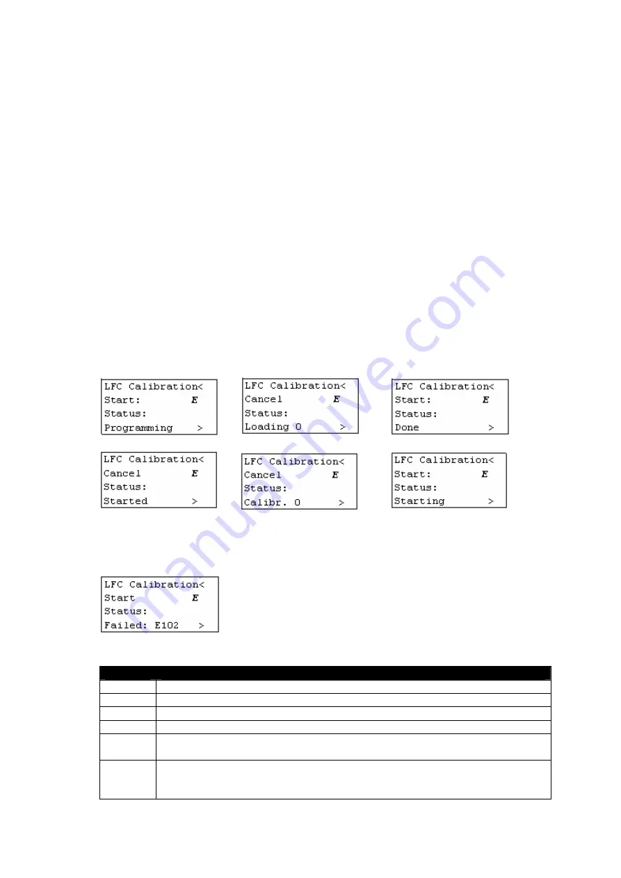
The different calibration steps:  

1.


LFC calibration firmware is loaded into the LFC hardware.  
The ‘Internal  2’ calibration table is copied to the ‘Internal 1’ calibration table. When 

the calibration is done ‘Internal 2’ will be overwritten with the new calibration data.  

2.


The LFC calibration software starts up and starts calibrating.  

The Start: changes in a Cancel. Pressing ENTER on it cancels the calibration. 
The progress is indicated on the keypad. Calibr. slowly increments from 0 up to 100. 

This is the longest step and takes approximately 8 minutes. The calibration itself can 
be followed on the OSD. (see further “OSD during calibration)  

3.


When the calibration is done, the calibration data is transferred (loaded) to the display 

main software.  

4.


The display main software programs the calibration data into non-volatile memory 

(into the ‘Internal 2’ table).  

5.


The LFC hardware is loaded with the LFC compensation firmware.  
The just calibrated table (‘Internal 2’) is loaded and LFC is enabled. 


Faults: 
If something goes wrong during calibration, the calibration is stopped and a fault code 
is displayed:  


The following error codes may appear:  
 

Code


Description


E4


Occurs during step 1 when the calibration firmware could not be loaded.


E5


Indicates a hardware problem.


E6


Indicates a hardware problem.


E7


Indicates a hardware problem.


E101


Could not load calibration software from flash. Flash on LFC hardware 
contains invalid or no LFC calibration software.


E102


Failure occurs during step 2, the test measurement fails. This could 
happen when the optical sensor is not placed on the front of the display 

or is not connected to the back.


Содержание ISIS LFC

Страница 1: ...ISIS LFC Installation Guide...

Страница 2: ...2 ______________________________________________________________ Barco ISIS LFC Installation Guide...

Страница 3: ...product contains material in which Barco retains proprietary rights Any act involving software reproduction or intervention is prohibited LFC Light Flicker Compensation is patent protected CA2327429...

Страница 4: ...splay that reside in the hardware interface of the display between the graphics generator and the LCD This feature compensates for LCD Flicker without affecting the displayed data Figure 1 1 shows a p...

Страница 5: ...Barco ISIS LFC Installation Guide ______________________________________________________________5 Figure 1 2 ISIS before and after LFC kit installation...

Страница 6: ...escription Quantity K5830190 G UN LFC POWER BOARD ISIS 1 Mainboard K5831010 UN JANUS BOARD CATCH 1 Mezzanine board K5830021 G UN MIC PROCESSOR LFC ISIS 1 K3494133 CD MDMD 15AWG26P15 200 1 cable K34941...

Страница 7: ...___________________________________________________________7 Figure 2 2 Wire ties and screws A new warranty label is added for attachment by a qualified person after installation according to the inst...

Страница 8: ...es For a safe handling of the display it is strongly recommended to mount at least temporary two handles as shown on the figure hereby Figure 2 3 Safe MDP 471 Handling Before starting the removal rein...

Страница 9: ...screw the 4x2 captive screws B and remove the Backlight Covers 4x Unscrew the 4x2 screws C 2 countersunk screws when present Unscrew the 2x4 screws D when a TS Cover is present Desktop version only Ca...

Страница 10: ...Figure 2 5 PIB power cord removal 1 Wire tie V348000 to be cut 1 1 Figure 2 5 PIB power cord removal Remove the AIB Analog Input Board K5830040 and the PIB Panel Interface Board K5830011 Remove the d...

Страница 11: ...at the decorative front plate side and a screw B361085 at the other side of the LFC Board I n p u t B o a r d Fan 2 Fan 1 P I B L F C B o a r d S l o t 2 S l o t 1 OP TICAL SENSOR J39 J38 Figure 2 6 B...

Страница 12: ...he yellow power cable Z3421999 with J1 on the PIB K5830011 Connect the cable K3494133 between J6 of the LFC Board K5830190 with J9 on the PIB K5830011 guiding the cable through the hole in the LFC boa...

Страница 13: ...ISIS LFC Installation Guide _____________________________________________________________13 1 hole in LFC Board 1 support plate Figure 2 9 PIB connection 1 Wire tie V348000 1 1 1 Figure 2 10 Cable fix...

Страница 14: ...cord 4 When Waiting for INTEL HEX data record has appeared or when the keypad or OSD says 0 lines received the upload can be started In softloader push the Upload button and select the new hex file to...

Страница 15: ...ternal 1 2 Internal 2 External uses the calibration table as stored in flash This table is the result of an external calibration Internal 1 2 use a calibration table as stored in the Panel EEPROM and...

Страница 16: ...Firmware Download Tool FDT software a KP Upload cable Z3498894 or equivalent a PC The needed items are included in the Barco ISIS Service Kit K5030070 The Z3498894 cable pinning is also described here...

Страница 17: ...ck Next 4 The software automatically tries to detect a Barco Protocol device Searching for BP device is displayed in the terminal window This takes a couple of seconds When the Barco Protocol device i...

Страница 18: ...splay responds with ve Error code 1 invalid command Important Do not continue if the software version doesn t match one of the following versions V2 04 V2 05 V2 06 V2 07 or V2 08 Contact Barco for ins...

Страница 19: ...t up when the Janus board was detected LFC will be enabled on start up when it was enabled before The LFC enabled disabled item will be available in keypad OSD menu s see Enabling Disabling LFC Admini...

Страница 20: ...used 2 2 3 2 Calibration Using the keypad navigate to the LFC advanced Submenu 1 Press the UNIF button on the keypad to go to the Administrator Menu Note The administrator password is required before...

Страница 21: ...bration itself can be followed on the OSD see further OSD during calibration 3 When the calibration is done the calibration data is transferred loaded to the display main software 4 The display main s...

Страница 22: ...llation Guide 2 2 3 3 OSD during calibration Figure 2 11 OSD during calibration Note The warning at the bottom Not calibrating on input signal is shown when no input signal is active during calibratio...

Страница 23: ...Barco ISIS LFC Installation Guide _____________________________________________________________23...

Страница 24: ...6 233 462 Barco Ortoghon AG Hastedter Osterdeich 222 28207 Bremen Germany Phone 49 421 20 12 20 FAX 49 421 20 12 29 99 BarcoView LLC 3059 Premiere Parkway Duluth Georgia 30097 4905 USA K5960011 00 ISI...

Отзывы: