background image


R5915190 /00 

IEX 

4                                                                                                       


IEX SE

R

IES


Instructions


About this chapter 

Read  this  chapter  attentively.  It  contains  important  information  to  prevent personal 

injury  while  installing  the  IEX  display.  Furthermore,  it  includes  several  cautions  to 

prevent  damage  to  the  IEX  tiles.  Ensure  that  you  understand  and  follow  all  safety 

guidelines, safety instructions and warnings mentioned in this chapter before installing 

the  IEX  tiles.  After  this  chapter,  additional 

warnings

” 

and 

cautions

  are  given 

depending  on  the  installation  procedure.  Read  and  follow  these 

warnings

” 

and 

cautions

” 

as well. 

Clarification of the term 

IEX

” 

used in this document 

When referring in this document to the term 

IEX

” 

means that the content is applicable 

for following Barco products: 

• 

LD IEX1.2, LD IEX1.2 RED PSU, LD IEX1.5, LD IEX1.5 RED PSU, LD IEX1.8, LD IEX1.8 

RED PSU, LD IEX2.5, LD IEX2.5 RED PSU


Barco  provides  a  guarantee  relating  to  perfect  manufacturing  as  part  of  the  legally 

stipulated terms of guarantee. Observing the specification mentioned in this chapter is 

critical for product performance. Neglecting this can result in loss of warranty. 


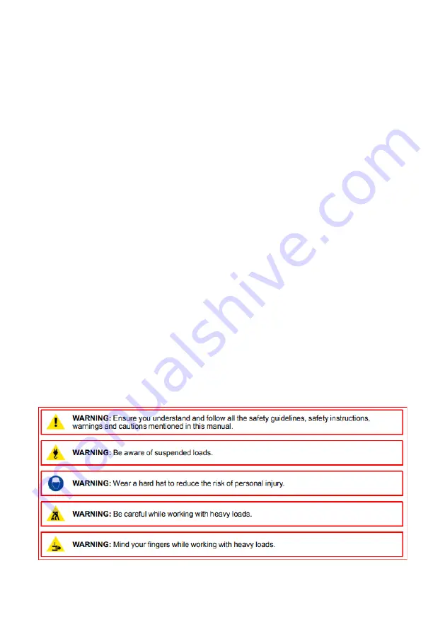
1.1 Safety guidelines 

Personal protection 


Содержание IEX Series

Страница 1: ...R5915190 00 IEX IEX SERIES Product Manual...

Страница 2: ...EX 1 IEX SERIES Barco NV Beneluxpark 21 8500 Kortrijk Belgium www barco com en support www barco com Registered office Barco NV President Kennedypark 35 8500 Kortrijk Belgium www barco com en support...

Страница 3: ...in this manual serve as comments or examples and are not to be understood as advertising for the products or their manufacturers Federal Communications Commission FCC Statement This equipment has been...

Страница 4: ...R5915190 00 IEX 3 IEX SERIES This product is fit for use in the UK Authorized Representative Barco UK Ltd Address Building 329 Doncastle Road Bracknell RG12 8PE Berkshire United Kingdom...

Страница 5: ...given depending on the installation procedure Read and follow these warnings and cautions as well Clarification of the term IEX used in this document When referring in this document to the term IEX me...

Страница 6: ...d the risk of the process of the operation A non professional operator should neither assemble nor disassemble these products by himself There is a risk of electric shock from exposure to high voltage...

Страница 7: ...s mechanical stability and strength enclosure construction and protection against the risk of fire Simulated single fault condition testing ensures the safety of the equipment to the user even when th...

Страница 8: ...ts must be undertaken immediately Protect the power data cords from being walked on or pinched particularly at plugs convenience receptacles and the point where they exit from the apparatus Replace da...

Страница 9: ...ccording EN61643 11 or UL 1449 is in place High leakage current The combination of multiple tiles in an installation results in increased levels of leakage current In order to avoid risk of electric s...

Страница 10: ...ility of destroying LED components do not touch either in operation or while switched off Always use ESD gloves Disconnect device When the appliance inlets of the individual tiles are not accessible t...

Страница 11: ...h new ones Never try to repair a power cord LEDs The LEDs used on the IEX tiles are fragile Never push with a hard or sharp object onto the lens of the LED as this may cause damage to the LED The maxi...

Страница 12: ...tion that will cause any part of the display to heat beyond what occurs during normal operation Such situations include but are not limited to lasers ultrasonic vibration or any type of substance that...

Страница 13: ...pment that is not CE and UL ETL certified When reconnecting components in an IEX tile care must be taken to ensure that cables are carefully routed according to the installation manual to prevent dama...

Страница 14: ...and humidity ranges for storage and operation Use of the products in temperature or humidity ranges outside these recommendations can cause temporary or permanent damages The SMD LEDs used on indoor...

Страница 15: ...al and Power Cable Connection 25 CHAPTER 3 LED DISPLAY CONTROL SETTING 27 3 1 POWER ON TESTING 27 3 2 STARTING THE HARDWARE 28 3 3 SOFTWARE CONTROL SETTING 28 3 3 1 Installing the Software 28 3 3 2 Di...

Страница 16: ...4 1 3 5 Playing the Media 63 4 1 4 Saving and Opening a Playing Solution 65 4 2 LED DISPLAY PLAYING SETTING 66 4 2 1 Set the Count and Size of the Screen 66 4 2 2 Setting the Program Page 67 4 2 3 Adj...

Страница 17: ...t in the Display 84 6 1 5 Failure in Lighting up of a Cabinet in the Display 84 6 1 6 Failure in Lighting up Part of the Modules in the Cabinet 85 6 2 REPLACEMENT OF MAIN COMPONENTS 86 6 2 1 Replaceme...

Страница 18: ...roduct in projects The IEX series can be assembled seamlessly into a screen of any size for different application environments 1 1 Features 1 Ultrathin lightweight and highly stable aluminium die cast...

Страница 19: ...earance 1 Upper lower shoulder screw hole 2 Signal and power socket 3 Positioning pin 4 Screw hole of fixing rear cover 5 Monitoring LCD 6 Handle 7 Test button 8 Nameplate 9 Left right shoulder screw...

Страница 20: ...r m 723 BTU hr m 436 BTU hr m Operation power voltage 100 240V 50 60Hz 100 240V50 60Hz 100 240V 50 60Hz 100 240V 50 60Hz Operational temperature 10 C to 40 C 14 F to 104 F 10 C to 40 C 14 F to 104 F 1...

Страница 21: ...cing controller and power distribution box The following shows a topology of the system for reference Figure 1 2 System Topology 1 5 Scope of Applications The IEX series products can be assembled seam...

Страница 22: ...found contact us in time The main components include cabinets signal cable power cable USB cable DVI cable and sending box For details about the components refer to the shipping list 2 2 General Insta...

Страница 23: ...p and from middle to both sides In addition fix the connecting plates and cabinets with installation screws to the square tubes 3 Keep proper joints and flatness between the cabinets during cabinet in...

Страница 24: ...2 4 Rear view of rear Installation Details Fig 2 7 M8x75 Inner hexagon bolt Fig 2 5 Front and Rear installation plate front Rear installation hole Fig 2 6 Front and Rear installation plate rear M8 75...

Страница 25: ...R5915190 00 IEX 24 IEX SERIES 2 3 Wiring for LED Display 2 3 1 Common cables Incoming Power Cable DVI cable Incoming Signal Cable long USB cable...

Страница 26: ...connection for cabinets with an arrangement of 4 cabinets Width 4 cabinets Height Signal cables shall be connected based on the wiring diagram of the delivered products for the project Figure 2 8 Sig...

Страница 27: ...n arrangement of 4 cabinets Width 4 cabinets Height Power cables shall be connected based on the wiring diagram of the delivered products for the project Figure 2 9 Power Cable Connection Diagram Rema...

Страница 28: ...e contact with the ground and kept away properly from the live wire The connected power supply shall be distant from high power equipment 3 When the 3 phase and 5 wire system is adopted the load shall...

Страница 29: ...een indicator of the sending box is blinking normally blinking once per second Figure 3 1 Replication Mode 3 3 Software Control Setting 3 3 1 Installing the Software Open the optical disk provided for...

Страница 30: ...k the User option and select Advanced Login as shown in Figure 3 3 Figure 3 3 Main Window of NovaLCT Mars Enter the initial password admin as shown in Figure 3 4 to go to the advanced user window Figu...

Страница 31: ...ure 3 6 Screen Configuration The following window is displayed Set Sending Board Resolution 1920 1080 recommended Set Graphics Output Resolution to the same value as Sending Board Resolution Then clic...

Страница 32: ...click Scan Board to display the following window Figure 3 8 Scan Board Configuration 1 Click Load File to load the file xxxx rcfg stored in the optical disk 2 Click Send to HW 3 After sending confirm...

Страница 33: ...uring the parameters on the Scan Board page click Screen Connection to display the following window 1 Click Read File to load the file xxxx scr stored in the optical disk as shown in Figure 3 9 Figure...

Страница 34: ...e screen is complete Then click Save Figure 3 10 Screen Connection with Loaded File 3 3 3 Brightness Adjustment On the main window click Brightness as shown in Figure 3 11 to display the brightness ad...

Страница 35: ...tness value the maximum value is 255 next to the scroll bar Figure 3 12 Manual Adjustment Display Quality Includes Soft mode and Enhanced mode The Soft mode is generally used for indoor LED displays w...

Страница 36: ...3 3 4 Correction Coefficient Management The IEX series products have been subject to correction before shipment To ensure the optimum displaying effect of the screen you need to activate the correctio...

Страница 37: ...atabase Set coefficients for a new scan board After replacing the scan board receiving card set the correction coefficients for the new receiving card Set coefficients for a new module After replacing...

Страница 38: ...As shown in Figure 3 15 select Topology or List Select the position of the replaced receiving card Click Next Figure 3 15 Selecting Area for New Receiving Card 2 Select the coefficient source Click B...

Страница 39: ...for Receiving Card 3 Select Stable Upload and click Next Figure 3 17 Uploading Correction Coefficients 5 Adjust Coefficient Perform a simple adjustment if the displaying effect is not good enough aft...

Страница 40: ...6 Save Coefficients Click Save to save the correction coefficients to the hardware The saved coefficients are retentive even after a power failure Then click Finish Figure 3 19 Saving Correction Coeff...

Страница 41: ...ext Figure 3 21 Selecting Position of New Module Module Size Set the size of the module in a cabinet The software determines each module arrangement based on module size and cabinet size 3 Adjust the...

Страница 42: ...nts to the hardware Use similar steps in setting coefficients for a new receiving card For details refer to Step 4 Step 5 and Step 6 in Section 3 5 1 so that they are retentive after a power failure F...

Страница 43: ...ure that the receiving have read coefficient from the Flash and save Click Setting on the main window and select Module Flash as shown in following fig Main Window Click Check Coefficient in Modules t...

Страница 44: ...e prestored picture for the screen This prestored picture can be set as a screen displayed upon booting signal cable disconnection or DVI signal absence On the main window click Tool and select Presto...

Страница 45: ...save the picture as a prestored picture to the hardware Click Check Store Picture to display the stored picture on the screen so as to check its effect 2 Function Settings Boot Screen Set whether to u...

Страница 46: ...greater than or equal to the actual screen pixel size Figure 3 25 Screen Size and Count 2 In the main window click Control By Point Calibration Brightness Calibration enter the calibration interface...

Страница 47: ...7 Brightness Calibration 4 Click Import By Region Normal to import the correction coefficient of the replaced spare module Figure 3 28 Brightness Calibration 5 Enter the location of the module that ne...

Страница 48: ...the corresponding area after importing the calibration file click Send to enable brightness correction Figure 3 30 Brightness Calibration 7 Open the LED screen setting window on the screen parameter...

Страница 49: ...R5915190 00 IEX 48 IEX SERIES Figure 3 31 LED Screen Setting...

Страница 50: ...ssional playing program and Priority programs of the page Professional playing program is used most This Section introduces the Professional playing program only Run the software to enter the main win...

Страница 51: ...To increase or decrease the number of display windows re enter the number of display windows in the box next to Number of Display Windows and then click Update Start X Indicates the horizontal start...

Страница 52: ...time when the PC is started Restart Software on Time If you enable this function set the restart interval and time and click OK NovaStudio will be automatically restarted after the PC time reaches the...

Страница 53: ...on the PC will automatically read and activate the playing solution once the USB flash drive is inserted to the PC If you do disable this function the PC cannot implement the plug and play function ev...

Страница 54: ...of the playing solution After adding a general time segment or interstitial segment click General Segment 1 to edit the properties displayed in the segment editing area on the right side as shown in F...

Страница 55: ...General Segment or click the Add Global Program Page in the toolbar to create a program page Figure 4 7 Creating a Program Page 2 Setting the properties After creating the program page click Program 1...

Страница 56: ...er the preset Times to Play for the display window with the longest playing time on the current program page has been reached If you select Specify Duration the next program page is played after the p...

Страница 57: ...in the area not covered by the display window as shown in Figure 4 9 Figure 4 9 Background of Program Page After adding the program page you can move copy paste or delete the program page by using the...

Страница 58: ...add a display window to this program page Click Add Window on the toolbar of the program page to add a window to the current program page See Figure 4 11 Figure 4 11 Adding a Window to Program Page A...

Страница 59: ...usted based on actual conditions by using either of the following two methods a Directly specify the new location and size in the setting pane as shown in Figure 4 13 Figure 4 13 Setting the Window Si...

Страница 60: ...eleted Click the delete key to delete the window as shown in Figure 4 15 Figure 4 15 Deleting the Display Window 4 Moving a display window Select the program or window Click the direction key to adjus...

Страница 61: ...dow for adding the media is Common Window Click the Add Media button of a common window to select media of different types to be added into the media list See Figure 4 17 Figure 4 17 Adding the Media...

Страница 62: ...On this property page you can change the properties of the medium See Figure 4 19 Figure 4 19 Properties of Medium 3 Editing the media in the common window In an actual application if different playin...

Страница 63: ...915190 00 IEX 62 IEX SERIES Modify Figure 4 20 Changing the Media Playing Times Right click the media to perform operations on the selected media as shown in Figure 4 21 Figure 4 21 Media Operation Me...

Страница 64: ...22 Figure 4 22 Media Playing Menu 4 1 3 5 Playing the Media After the playing mode is edited or loaded click the play key on the main toolbar to start the current playing mode as shown in Figure 4 23...

Страница 65: ...tion Page Clicking Pause or Stop on the toolbar can pause or stop the currently played program You can also perform this operation by using the operation menu that appears when you right click the dis...

Страница 66: ...w you need to click Pause perform the Move Up operation to move the clock window to the front side of the common window and then click Play If the clock is displayed transparently the clock will overl...

Страница 67: ...lect Open to open the playing solution See Figure 4 28 4 2 LED Display Playing Setting 4 2 1 Set the Count and Size of the Screen Open the software click Control Screen Size and Count Settings in the...

Страница 68: ...lobal Page The program page that is played continuously during playback can contain multiple windows Only one global page can be set per screen Normal Page The normal page can contain multiple windows...

Страница 69: ...R5915190 00 IEX 68 IEX SERIES Figure 4 32 Adding New Program Page 2 After creating the program page click the Add button or right click on the program page node to bring up the add program window menu...

Страница 70: ...R5915190 00 IEX 69 IEX SERIES Figure 4 33 Add Program Window Menu 3 After adding the file window select the file window and click the Add button to select the desired material...

Страница 71: ...R5915190 00 IEX 70 IEX SERIES Figure 4 34 Material Menu 4 After adding the material can set the material properties in the property box as shown below Figure 4 35 Display Setting Interface...

Страница 72: ...th of the window in pixels Height The height of the window in pixels Window operation icon For window shortcuts there are left right top bottom and maximize Border To set the width of the window borde...

Страница 73: ...ain window Play Play to start playing Figure 4 38 Play the Current Program File 2 Play multiple programs at the same time Set the playback content click the program page that want to play or click the...

Страница 74: ...hat want to copy click the Copy button click the copied location and click the Paste button 3 Save After making the desired program page click the button to save the button or click File Save to save...

Страница 75: ...pause play program power on LED display power off LED display show on LED display show off LED display set brightness show LED play screen hide LED play screen restart this application close this app...

Страница 76: ...R5915190 00 IEX 75 IEX SERIES Figure 4 45 Action Table Figure 4 46 Timing Command List...

Страница 77: ...5 1 Startup Sequence 1 Start the distribution box for the LED display 2 Start the control computer 3 Start the video processor 4 Start the sending box 5 2 Shutdown Sequence 1 Shut down the video proce...

Страница 78: ...ether the power cables and signal cables for the LED display are connected securely and safely and whether the display is grounded reliably 5 Check whether the steel structure is secure on a yearly ba...

Страница 79: ...R5915190 00 IEX 78 IEX SERIES Figure 5 1 Prestore Picture Setting...

Страница 80: ...terface as shown in Figure 5 2 Figure 5 2 Main Window for Advanced User Select Manual and set the brightness to 13 the brightness is about 5 by dragging the scroll bar below Brightness Adjustment See...

Страница 81: ...EX SERIES Return to the main window Click Display Control to enter the Screen Control interface Set Self Test to White Click Send to finish the operation As showed in Figure 5 4 and Figure 5 5 Figure...

Страница 82: ...play is not used for 14 consecutive days please follow the instructions below for aging before using it again In the main window click Test Aging Test to enter the aging interface Drag the playback wi...

Страница 83: ...R5915190 00 IEX 82 IEX SERIES Figure 5 6 Aging Test Figure 5 7 Screen Test...

Страница 84: ...ck whether the control PC is in sleep mode or monitor protection mode If the control PC is not in sleep mode check whether the graphics card is configured properly on the software 6 1 2 Incomplete Pic...

Страница 85: ...esolution of the screen 6 1 4 Blinking of a Cabinet in the Display Causes 1 The output of receiving card or hub card is faulty 2 The receiving card program is incorrect Troubleshooting method 1 Check...

Страница 86: ...the Modules in the Cabinet Causes 1 Output of the power supply for the modules is faulty 2 Output of signal which controls the related modules is faulty Troubleshooting method 1 Check DC voltage for...

Страница 87: ...the power supply to ensure your personal safety and equipment safety When replacing the module please pay attention to the direction of the module Replace a module of the LED display based on the fol...

Страница 88: ...aintenance step Step 1 Use a screw driver to remove 4 bolts which fixed the back cover Step 2 Pull out the connecting cable of the back cover and remove the back cover Step 3 To remove the module from...

Страница 89: ...new power supply pay attention to the order of the power cables to prevent short circuits Replace a power supply of the LED display based on the following steps Front maintenance step Picture Descrip...

Страница 90: ...ture Description Step 1 Use a screw driver to remove 4 bolts which fixed the back cover Step 2 Pull out the connecting cable of the back cover Step 3 Remove the rear cover and loosen the four bolts of...

Страница 91: ...ard pay attention to the direction of the receiving card Replace receiving card of the LED display based on the following steps Front maintenance step Picture Description Step 1 Disconnecting the powe...

Страница 92: ...step Picture Description Step 1 Use a screw driver to remove 4 bolts which fixed the back cover Step 2 Pull out the connecting cable of the back cover and remove the back cover then you can see the r...

Страница 93: ...ation The product shall not be placed upside down or horizontally and must be protected against the wind rain direct sunlight and corrosive liquid during transportation The stacking layers shall not e...

Страница 94: ...ecycling of waste electrical and electronic equipment To prevent possible harm to the environment or human health from uncontrolled waste disposal please separate these items from other types of waste...

Страница 95: ...0 00 IEX 94 IEX SERIES Importers contact information To find your local importer contact Barco directly or one of Barco s regional offices via the contact information given on Barco s web site www bar...

Отзывы: