background image

24. Lens shift assembly

Image 24-2

24.1 Lens shift assembly motors

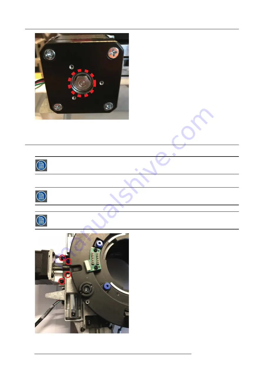
1. Remove 4 screws (M3x8 TX10 W/Lockw.) to remove lens shift motors with lead screw from lens shft assy.

Dependent on the position of the lens shift mechanism, it may be necessary to manually turn leadscrew to
expose the screws (8mm hex). Accessing these, removal of complete assembly is necessary.

2. Remove 4 screws (M3x8 Tx10) to release lens shift motor from holder.

- Motor for horizontal shift (left) connects to PCB lens hub connector J1

- Motor for vertical shift (lower) connects to PCB lens hub connector J2

Image 24-3

124

723–0016 F90 01/12/2017

Содержание F90 series

Страница 1: ...F90 Service Manual 723 0016 02 01 12 2017...

Страница 2: ...Barco Fredrikstad AS Habornveien 53 N 1630 Gamle Fredrikstad Norway Phone 47 6930 4550 Fax 47 6930 4580 Support Support fre barco com Visit us at the web www barco com Printed in Norway...

Страница 3: ...orm 19 5 4 Wiring Matrix 21 5 5 Firmware 22 5 6 System Safety Loop 22 5 7 Laser driver Principle and error codes 24 6 GP6 periodical maintenance 27 6 1 Service Interval Matrix 27 6 2 Service Kits avai...

Страница 4: ...indications 63 17 2 LED s on Thermal Hub and Mainboard 63 17 2 1 Thermal Hub Board LED s 63 17 2 2 Main Board LED s 64 17 3 Available Diagnostic Tools 65 17 3 1 Prospector 65 17 3 2 pd Diagnostic 66 1...

Страница 5: ...113 22 2 5 Mirrors Blue 114 22 2 6 390 Blue loop lens 3 114 22 2 7 390 Blue loop lens 4 114 22 2 8 Diffusor blue loop 115 22 2 9 390 RGBY Converging Lenses 115 22 2 9 1 Converging Lens Entrance 115 2...

Страница 6: ...Table of contents 4 723 0016 F90 01 12 2017...

Страница 7: ...em without prior written consent of Barco 1 3 Trademarks Trademarks Brands and product names mentioned in this manual may be trademarks registered trademarks or copyrights of their respective holders...

Страница 8: ...1 Introduction 6 723 0016 F90 01 12 2017...

Страница 9: ...2 Notice on safety Safety This equipment is built in accordance with the requirements of the international safety standards IEC60950 1 as basis for National safety regulation world wide The safety sta...

Страница 10: ...2 General safety 8 723 0016 F90 01 12 2017...

Страница 11: ...ctor Should any liquid or solid object fall into the cabinet unplug the set and have it checked by qualified service personnel before resuming operations Do not disassemble this projector always take...

Страница 12: ...nd that the projector complies with Electromagnetic Compatibility EMC requirements it should only be operated when all of its covers in place Always remove lens cap before switching on the projector I...

Страница 13: ...exhibits a distinct change in performance indicating a need for service Replacement parts When replacement parts are required be sure the service technician has used original Barco replace ment parts...

Страница 14: ...d replacement of optical components After reassembly of Cluster Laser interface and TI Loop the unit must be properly tested against leak of light due to improper reassembly of the parts This test mus...

Страница 15: ...rds the dichroic mirror where it is transmitted and focused onto the dual rod system A small portion of the blue light is transmitted through a clear segment of the PW and is relayed around to the bac...

Страница 16: ...ale image Grayscale Image 4 3 Image 4 4 A DMD panel s micro mirrors are mounted on tiny hinges that enable them to tilt either toward the light source in a DLP projection system ON or away from it OFF...

Страница 17: ...ystems and business projectors using DLP technology rely on a single DMD chip configuration like the one described above White light passes through a color wheel filter causing red green and blue ligh...

Страница 18: ...4 DLP System General Description 16 723 0016 F90 01 12 2017...

Страница 19: ...t Light Output especially in multi projector setup and Lens Shift Motors It is crucial that all SD card data is transferred to the replacement PCB in the event of repair Failure to do this will compro...

Страница 20: ...d LCD screen Peripheral PCB i e IR Sensors USB input Keyboard Display Phosphor wheels Color wheels Safety Switches Air inlet temp sensor Air out temp sensor Communication with Thermal Hub Board and PS...

Страница 21: ...PHY s MUX es EQ s 512MB FLASH SPI 128MB FLASH SPI USB 1 OTG Trigger Out 1 2 Internal SPI buses Internal I2C bus structure ECO MODE Controller DC DC Internal Clock Distribution Internal Reset Structure...

Страница 22: ...Inlet sensor CW Laser Bank 4 6 Laser Bank 1 3 IR Top Fan IR DP Sensor NTC Peltier LED IR_L Fan PSU Fan Laser Fan Optics USB Trigger Fan PSU Fan LaserDrivers Fan Optics Peltier NTC Dewpoint IR Front F...

Страница 23: ...300 1 Thermal Hub Board J4 Motor Illumina on Iris 534 0026 01 400 0909 00 Cable Motor Lens Shi 320 1 Thermal Hub Board J1 Motor Lens shi 534 0027 03 Switch Iris 390 2 Thermal Hub Board J37 Switch Iris...

Страница 24: ...ndividual for each and every colorwheel Consequently after replacing the colorwheel index adjustment must be performed in the service menu 5 6 System Safety Loop System Safety Loop The projector is eq...

Страница 25: ...5 GP6 system functional description Image 5 5 723 0016 F90 01 12 2017 23...

Страница 26: ...ing the error The NTC s on the Laser driver board are defines as heatsink in the error message string and the NTC s on the laser banks is defined as bank in the error message string The error message...

Страница 27: ...heatsink0 errorinput Laser driver board 1 Upper e20400 environment laser board1 heatsink1 errorinput Laser driver board 1 Upper e20400 environment laser board1 heatsink2 errorinput Laser driver board...

Страница 28: ...5 GP6 system functional description 26 723 0016 F90 01 12 2017...

Страница 29: ...which must be replaced at each service interval the quantity needed and the article number The item descriptions does not necessarily reflect the description in the parts list Service Interval Matrix...

Страница 30: ...x Fan Blower 38x37 1 pc Fan Optics 1 R9801434 GP6 Cooling kit 40k hours 504 0623 00 Fan 119x25 24v PWM Cooling of radiators 5 pcs 504 0623 00 Fan 119x25 24V PWM Laser driver 1 pcs 502 0372 00 Liquid c...

Страница 31: ...y on the keypad until this menu appears Then use the arrow keys and the confirm key to navigate in the menu The different choices in the menu are mainly self explanatory and open for all users The exc...

Страница 32: ...confirm each number by the confirm key When the complete code is entered select Return and OK Image 7 3 When inside the Service menu this menu will appear Each choice in this menu has sub menus Each...

Страница 33: ...7 OSD display menu Image 7 4 7 2 Troubleshooting tools The Barco Prospector application can be used for troubleshooting and diagnostics 723 0016 F90 01 12 2017 31...

Страница 34: ...7 OSD display menu 32 723 0016 F90 01 12 2017...

Страница 35: ...ilters means there is no risk of clogging and more air is continually moved through the system resulting in lower operating temperatures over time and longer time between maintenance procedures Coolin...

Страница 36: ...8 Thermal management system Image 8 1 34 723 0016 F90 01 12 2017...

Страница 37: ...or 1 2 3 4 5 Driver are all axial flow fans which operate by increasing the pressure of air flowing through it There are six 6 axial fans 119x25 5 in the system 5 pcs for the radiators and 1 pcs for t...

Страница 38: ...atsink is a heat pipe construction combined with a dual Peltier module This ensures that the DMD device operates within its recommended thermal envelope and connects it physically to the Heatsink A sp...

Страница 39: ...2810 2802 2794 Radiator 5 2880 2875 2873 2870 2858 2850 2836 TMboard0bank0 C 43 0 48 0 51 2 51 8 52 1 53 4 57 9 TMboard0bank1 C 41 6 46 7 49 8 50 5 50 8 52 0 56 6 TMboard0bank2 C 43 3 48 3 51 5 52 3 5...

Страница 40: ...840 2829 2821 2805 2791 Radiator 5 2885 2880 2876 2869 2855 2842 2831 TMboard0bank0 C 32 16 37 32 41 9 45 74 49 54 06 59 04 TMboard0bank1 C 30 9 36 0 40 6 44 5 47 7 52 8 57 7 TMboard0bank2 C 32 9 38 0...

Страница 41: ...e 8 4 Ref also chapter 19 2 7 Cooling Pump Connection Map Naming of the pumps vs the fans Fan name Corresponding pump goes to Pump No Connector No Fan 1 Left Cluster Back 2 2 Fan 2 Left Cluster Top 1...

Страница 42: ...8 Thermal management system 40 723 0016 F90 01 12 2017...

Страница 43: ...at importance to disable the Lens Shift function when the mechanically lens lock is performed If not the shift mechanism will be possible destructed if lens shift accidentally is performed when the me...

Страница 44: ...ted by the red and green circles in the illustration below Tighten the screws with a sufficient torque The green circles indicate the lock for the vertical shift and the red circles indicate the lock...

Страница 45: ...rough adjustment of the TI Loop mirror All these elements contribute towards providing the brightest sharpest and most uniform image as possible in this class of projection 10 2 Lightning Mirror adjus...

Страница 46: ...Relay tube lens focus adjustment Adjust NUBs A B until the edges of both mirrors are visible in the projected image See above picture A Turn stub screw counter clockwise to loosen 1 Adjust by pushing...

Страница 47: ...e white point in edges of image and compare Note In order to adjust one leg accurately the alterative light source must be shut off See chapter 13 3 for details 1 2 Image 10 7 If a yellow spot can t b...

Страница 48: ...iformity Final verification Use Prospector and enable both laser clusters Measure on each side of image and center using a radio spectrometer Aim is to have max 0 005 differences Cx and Cy between the...

Страница 49: ...ompromising color saturation This configuration may be used where color accuracy may be traded off for higher brightness The hub on each motor has a black index mark applied so that the system can det...

Страница 50: ...rved distortion start point Find the exact point where the disturbance is visible and note the value that appears to the right of the Clean Up Wheel slider 3 Move the slider to the right until the dis...

Страница 51: ...a web browser and enter http xxxxxx 9999 where xxxxxx is the IP address for the projector and 9999 are the code for entering Prospector As an example http 192 168 1 100 9999 The IP Address for the pr...

Страница 52: ...rvice menu and use the mouse or PC arrow keys to move the slider until the test picture become slightly lighter yellow color starts to intrude in to the picture Continue to adjust the slider to find t...

Страница 53: ...0 329 and reduce it if s lower than 0 329 The goal is to set the laser pulse value so that the white ypoint is 0 329 6 Go back to the native RealColor P7 menu item and update the x and y value for whi...

Страница 54: ...ame procedure for Green and Blue Note Do not use C1 if you use brilliant color video mode C1 is used only if you use brilliant color native mode You have now defined the projector the projector now kn...

Страница 55: ...he new XPS actuator part note the resonance frequency for the new unit This number is written on the XPS actuator label This number is important for later calibration of the replacement part Image 14...

Страница 56: ...he unit changes to 4K UHD and the XPS actuator are switched on The Xpr cross test picture occurs on the screen Select the Resonance slider and set the Resonance to the same value as on the new XPS act...

Страница 57: ...14 XPS actuator XPR Cross Test pattern views Optimal Center Cross position in 4K WQXGA Mode Center cross position in 4K WQXGA Mode with gain out of adjustment Image 14 6 723 0016 F90 01 12 2017 55...

Страница 58: ...14 XPS actuator 56 723 0016 F90 01 12 2017...

Страница 59: ...f serviced Each contact point of the CLGA is a C shaped spring which secures adequate tension between pads on DMD boards and the DMD chip Important Do not use wipes to clean the CLGA as microscopic pa...

Страница 60: ...15 Light engine 58 723 0016 F90 01 12 2017...

Страница 61: ...ojector label only No rating on PSU label R7681400 110 240V 50 60Hz 16 12A For projector label only No rating on PSU label 16 2 Output specification The output connectors contain output voltages from...

Страница 62: ...16 Power Supply Unit PSU 16 3 Connectors Image 16 1 16 3 1 PSU Control connector HDMI C Image 16 2 60 723 0016 F90 01 12 2017...

Страница 63: ...in 7 12V 1_GND Pin 8 12V 1_GND Pin 9 11 5V_STB_GND Pin 10 SGND Shield GND Image 16 3 16 3 3 Thermal Hub Connector PIN Nr Output name Molex Microfit SEEN FROM ABOVE http www molex com pdm_docs sd 43045...

Страница 64: ...ND Shield GND Pin 7 LASER Driver supply 2 Pin 8 Not used Pin 9 GND_LASER Driver supply Pin 10 Not used Pin 11 Not used Pin 12 SGND Shield GND Image 16 5 16 4 Power supply diagnostic 16 4 1 Power good...

Страница 65: ...figures below show the failure matrix and the location of the different LED s 17 2 1 Thermal Hub Board LED s Thermal Hub board failure indications Ref Des Component No Function Failure Illumination co...

Страница 66: ...outside spec DS24 Supply voltage fail 0V9 Red 0V9_GXB Voltage outside spec DS25 Supply voltage fail 1V0 Red 1V0 Voltage outside spec DS26 Supply voltage fail 1V8 Red 1V8_GXB Voltage outside spec DS27...

Страница 67: ...lable Diagnostic Tools 17 3 1 Prospector Notifications in Pulse Prospector PROSPECTOR internal web interface which provides a real time operation overview including voltage levels temperatures fan spe...

Страница 68: ...n Has a timeout 17 3 5 LCD Notifications in LCD When OSD in not active and LCD is active Pressing ok clears the notification Has a timeout 17 4 Troubleshooting About this chapter This chapter enumerat...

Страница 69: ...b Laser Driver Board SMPS PSU Formatter Color wheel B Board detection I Input Physical location Indicates the source of the error Physical location Value Comments Mainboard 00h Laser driver 0 A labell...

Страница 70: ...at the front air inlets of the projector Check airflow of the projector Make sure the projector operates within specs and make sure that the installation requirements are fulfilled Code E0000101 Main...

Страница 71: ...re exceeded Error Situation Solution This error appears alone Insufficient air flow through laser driver housing check for clogged vents OR the laser bank connected to the affected driver output may b...

Страница 72: ...0400 LaserDriver A heatsink 4 temperature reading failure Error For this error the same troubleshooting table can be applied to as for code E1000400 LaserDriver A heatsink 1 temperature reading failur...

Страница 73: ...ble can be applied to as for code E1000400 LaserDriver A heatsink 1 temperature reading failure Code E2200101 LaserDriver B bank 3 temperature exceeded Error For this error the same troubleshooting ta...

Страница 74: ...sue Remove the mainboard from the projector Check reseat the wire unit of the fan If problem persists replace the fan Malfunction Mainboard Replace the Main Board Fan end of life Replace the fan Code...

Страница 75: ...rce is connected with the pump and heat exchanger Code E9000000 PSU mainpower low limit reached Error Situation Solution Internal Power Supply not functioning well due to incoming mains voltage too lo...

Страница 76: ...s not blocked Check the fan wiring Replace the PSU See service procedure Code E9000601 PSU Heatsink2 temperature exceeded Error Situation Solution Potential malfunction of the PSU Heatsink2 temp too h...

Страница 77: ...ile Image 17 4 Buttons allow to provide dedicated log files Standard log functionality Log01 The standard log functionality is the log file that should be attached the service ticket when a problem is...

Страница 78: ...ignin 2 Click on Products to display the All Product categories page 3 Click on All products A Z at the right side of this page to display the Alphabetical product listing page 4 Select your F80 Serie...

Страница 79: ...be found in the directory media sdcard log 3 Open the newest folder 4 Open the messages file using e g Notepad Image 17 8 5 Search for words Error Warning in the text file for guidance in toward find...

Страница 80: ...xxxxxxxxxxxxxx Where timestamp xxxx xx xxxxx xx xx xxxxxxz the time when the event occurred code xxxxx unique numeric code of the event which indicates also the source of the event severity xxxx the s...

Страница 81: ...18 Assembly Hierarchy 18 ASSEMBLY HIERARCHY 18 1 Hierarchy overview This section describes which parts need to be removed in order to access faulty parts Image 18 1 723 0016 F90 01 12 2017 79...

Страница 82: ...18 Assembly Hierarchy 80 723 0016 F90 01 12 2017...

Страница 83: ...wing items may retain a charge DC Power supply Laser Driver Take care when removing the cluster module In the unlikely event that the bulb ruptures small glass frag ments may be generated The cluster...

Страница 84: ...ed circle securing the front cover Pull out the front cover in the direction indicated with the arrow Repeat this step for the front cover and screws on the other side of the lens opening as well The...

Страница 85: ...is removed due to the two cables that still are connected to the pcb on the inside of the side cover 3 Disconnect the Flex Cable from the Back Panel PCB by gently lifting up the tab on the connector...

Страница 86: ...sure to position the tabs in an upwards position as indicated by the red arrow Location of IR receiver board Image 19 12 Observe the tab Image 19 13 IR receiver assembly 19 3 2 PCB Front USB Trigger...

Страница 87: ...e radiator back 2 Disconnect the cable and remove one screw T8 M2 5x6 Note Do not touch components on the board directly during handling always hold the board edges Image 19 16 19 3 5 PCB Inlet temp s...

Страница 88: ...2 1 4 Remove the left side cover and perform this procedure 2 Remove 6 screws indicated by the blue circles to remove the complete display and keypad module from the side cover 3 For splitting the ke...

Страница 89: ...ave been replaced it may be necessary to do an index adjustment of the color wheel and or phosphor wheels See chapter Colorwheels page 47 for details All service intervals shall be carried out by auth...

Страница 90: ...g to the procedure described in chapter Entering Prospector diagnostic tool page 49 20 2 2 Fan Phosphor wheels 2 pcs 1 Remove the 2 screws holding the PW duct bracket in place Tx10 M3X6 2 Lift fan fro...

Страница 91: ...y align these properties in the system 1 Remove projector main covers as described in section 9 2 1 2 Release 3 captive screws to open CW cover 3 Release 3 captive screws to release CW Image 20 7 Imag...

Страница 92: ...an cable from the PCB thermal hub connector J26 2 Disconnect the large brown LVDS flex cable on the PCB thermal hub side 3 The fan PCB is mounted in a rubber frame under the PCB and held in place with...

Страница 93: ...te fan from bracket by releaseing 4 screws TX20 M4x10 Image 20 16 20 2 5 Laser Clusters Blue 2pcs About In order to ease access to the laser clusters the PSU may be removed See PSU page 136 The GP6 ha...

Страница 94: ...rations The procedure is identical for both the laser clusters 1 1 Disconnect 2x3 power connectors on each laser bank indicated by red ovals on the picture below 2 2 Remove 4 4 screws T10 M3x10 w wash...

Страница 95: ...cluster falling to the bottom 6 6 Position the new laser cluster to the Laser Interface Ensure that the cluster is properly in place The cluster will fall in to a track and it will not be possible to...

Страница 96: ...ng pump surface 1 1 Remove old thermal gasket using a plastic card or similar Caution Do not use metallic materials 2 2 Clean copper surface with an optical cloth and Isopropanol or brake clutch clean...

Страница 97: ...ector 1 and so on Image 20 27 In order to activate the new thermal conductive change material gasket used on the laser clusters the unit should be kept with lasers running at full power for 1 hr 20 3...

Страница 98: ...he fan assy Note The fan can also be removed without removing the complete fan and bracket assembly by only performing step 2 Image 20 28 Image 20 29 Mounting details Overview of Fan Laser driver and...

Страница 99: ...32 Exploded view of the fan and radiator assembly For illustration purposes the in the service manual the complete inlet cooling system has been split in three frames sections 1 Frame radiator left Co...

Страница 100: ...ns from the frame 6 Remove 8 scres securing each metallic grid 7 Remove 8 screws Tx10 M4x8 and swap the 2 radiators cooling pumps Image 20 35 Image 20 36 8 The new liquid cooling pumps are equipped wi...

Страница 101: ...pumps without removing laser drivers but that requires you have flexible hex tools It will be an advantage to loosen the pump modules as the first step to minimize stress on the tubes for the cooling...

Страница 102: ...ce also needs to be cleaned 1 Remove old thermal gasket using a plastic card or similar no metallic items 2 Clean copper surface with an optical cloth and Isopropanol or methylated spirit Image 20 40...

Страница 103: ...20 Scheduled operations Image 20 42 Image 20 43 723 0016 F90 01 12 2017 101...

Страница 104: ...20 Scheduled operations 102 723 0016 F90 01 12 2017...

Страница 105: ...tighten the screws in diagonal order All dove clamp screws shall be tighten wit a torque of 3 1Nm 21 1 DMD assembly Location The DMD assembly is highlighted in the illustration below Image 21 1 Locati...

Страница 106: ...nk assembly by removing 4 4 screws TX10 M3x8 using an X sequence Image 21 3 Note Heatsink stud and cooling surface may be bonded to DMD and Front side heatsink by the thermal paste Some force may be r...

Страница 107: ...A with DMD back onto heatsink assy with correct orientation as shown in illustration above The text on the back of DMD should be readable 21 5 Re assembly after PCB DMD or DMD CLGA repair 1 lean the s...

Страница 108: ...front and rear assy is separated during service Peltier element will most probably follow the Heatsink Rear assy Dependent of level of repair the Peltier element may have to be released and moved This...

Страница 109: ...ated heatsink Image 21 11 Image 21 12 4 Clean the Stud and Peltier surfaces with Isopropanol or Clutch Brake cleaner 5 Add phase change material 390 Gasket TIM Peltier on Peltier Remove thin plastic f...

Страница 110: ...this operation Temp sensor and safety switch must be loosened before removing laser interface Take note of the spacer below the left laser interface 1 Release two screws TX20 m50X45 opening the Dow Ta...

Страница 111: ...op will be narrow and paralell 3 Hold the interface in place with one hand while entering the two M4x12 screws and thereafter apply the clamps and tighten them up Ensure correct position and fit also...

Страница 112: ...21 DMD DMD Board CLGA DMD heatsink elements 110 723 0016 F90 01 12 2017...

Страница 113: ...the unprotected fingers will cause overheating and damage of optical components Left and right TI Loops are identical modules But the right module is turned upside down related to the left module in o...

Страница 114: ...CLO Lens banana board End switch PW left PW right Color wheel IR LED Laser Cluster connectors Laser Cluster connectors End switch Image 22 2 22 2 1 TI Loop Left 1 Remove 3 outer screws Tx10 M3X6 Mark...

Страница 115: ...ror corner indicating the direction of the dichroic filter Image 22 6 22 2 4 Barrel PW Lens assy This kit contains two lenses A B These were earlier assembled and offered as two separate assemblies Th...

Страница 116: ...not conflict with the Top Cover The red mark on the blue mirror should point INWARDS as shown in picture Image 22 9 22 2 6 390 Blue loop lens 3 1 1 Remove screw Tx08 M2 5x6 2 2 Remove the clip holding...

Страница 117: ...use finger cots or gloves when handling lens elements NOTE direction of lens when reinstalled The flat surface should be facing outwards towards Laser cluster curved concave side in NOTE direction of...

Страница 118: ...ng the clip and lens Image 22 16 Image 22 17 22 2 10 Adjusting Mirror 1 2 Remove 2 screws TX8 M2 6x6 2 2 Pull clips in the direction of the red arrow using a sharp implement e g tip of scalpel and rep...

Страница 119: ...urn the TI Loop upside down open the lid of the phosphor wheel compartment 6 Remove the air guide to access screws below 7 Release 3 screws securing phosphor wheel to access 2 new screws below 8 Remov...

Страница 120: ...Washer wedge pointy end must point toward Rod exit side to ensure Rod is pressed correctly against exit of hollow rod Do NOT touch surfaces of glass rod with bare hands This will drastically reduce li...

Страница 121: ...sensor Constant Light Output GP6 Iris assy and Relay Tube assy can be removed without removing illumination engine Adjustable mirror and CLO can only be accessed after removing the complete engine cor...

Страница 122: ...er Image 23 4 Releasing iris assembly from the cover 23 2 Relay Tube assy 1 Remove two screws TX8 M2 5x6 the clips and carefully lift out assembly 2 In order to place the lens in correct position when...

Страница 123: ...ation Engine In order to access screws releasing mirror complete engine Core including lens shift must be removed Mirror adjustment may be needed after this procedure 23 4 1 Removing Folding Mirror as...

Страница 124: ...23 Illumination Engine front Tip See Optical adjustment Optical adjustments page 43for adjustment of mirror after service 122 723 0016 F90 01 12 2017...

Страница 125: ...ical End H 3 504 0087 xx PCB Lens conn Pogo pin board 4 Lens lock scheimplug screws 1 2 3 4 Image 24 1 These components are all accessible removable without taking out the complete lens shift assembly...

Страница 126: ...ens shift mechanism it may be necessary to manually turn leadscrew to expose the screws 8mm hex Accessing these removal of complete assembly is necessary 2 Remove 4 screws M3x8 Tx10 to release lens sh...

Страница 127: ...connects to PCB lens hub connector J18 Lower limit sensor for vertical shift connects to J19 Image 24 4 24 3 PCB lens connectors 1 Release 2 screws M3x8 TX10 to remove each PCB lens conn Left PCB is...

Страница 128: ...Image 24 6 24 5 Scheimpflug screws Lock nut and adjustment screws are separately available order 24 6 Lens shift assembly and optical actuator 1 Remove 4 screws TX20 M4x12 available from inside lens o...

Страница 129: ...removed Note See XPS actuator page 53 for details tuning new actuator if it has been replaced Image 24 10 24 7 TIR Prism Use cotton gloves or finger nuts whenever handling the TIR prism 24 7 1 Remove...

Страница 130: ...the prism out carefully Image 24 13 24 7 2 Cleaning the TIR prism 1 Use ionized air when cleaning the TIR prism 2 If the unit is extremely dirty use a nonabrasive optical wipe and optical cleaning sol...

Страница 131: ...Reassemble the TIR prism 1 Insert the prism in the engine housing 2 Gravity naturally places the prism in the correct position towards the contact faces 3 Push in the Prism Clip and fasten the 4 screw...

Страница 132: ...24 Lens shift assembly 130 723 0016 F90 01 12 2017...

Страница 133: ...Gently remove complete bellow and lens ring the lens shift cable is routed via the bellow and must be disconnected 3 Remove 4 screws TX20 M4x12 available from inside engine Image 25 1 Image 25 2 4 Re...

Страница 134: ...25 Prism Housing Image 25 5 132 723 0016 F90 01 12 2017...

Страница 135: ...ight Larger F PW_R Largest Cable Routing 1 Switch Thermal Bimetallic witch loop1 Laser Driver 1 Output Comm Phosphr wheel 1 2 Switch Thermal Bimetallic witch loop2 Laser Driver 2 Output Comm Phosphr w...

Страница 136: ...ing the following procedures the PCB lens hub board including bracket Hub board top and bottom can be removed 1 Disconnect all cables remove 4 screws Tx10 M3x6 2 Release 2 screws Tx10 M3x8 towards the...

Страница 137: ...rd 2 HDMI 6 Lenshift H Horizontal 24 Peltier F 7 Lenspos H Hor 25 NTC F 8 Lens 26 FAN PCB 9 FPCA HK JTAG Not in use 27 Mainboard 1 HMDI 10 Fan 28 Fan IR L FS90 only 11 Lensshift V Vertical 29 NTC R NT...

Страница 138: ...26 7 Image 26 8 26 4 PSU Removing the PSU to access the laser clusters in not essential but will make the procedure easier The PSU can be removed without first removing PCB Main and sheet metal bracke...

Страница 139: ...separately in the unlikely event of malfunction The complete assembly laser driver pair can be removed to gain access to other parts of the projector 26 5 1 Remove the Laser driver cage 1 Disconnect t...

Страница 140: ...he two HDMI cables 2 2 Disconnect the Power inlet connectors 3 3 Remove 14 screws Tx10 M3x6 and carefully lift out the PCB Laser driver Image 26 13 26 5 3 Remove the Bottom laser driver PCB board 1 Re...

Страница 141: ...26 Technical Operations Image 26 14 4 For further access to the optical engine remove the bracket frame center 4 screws T10 M3x6 and 1pcs T20 M4x10 Image 26 15 723 0016 F90 01 12 2017 139...

Отзывы: