background image

B. Barco Control Manager

Security

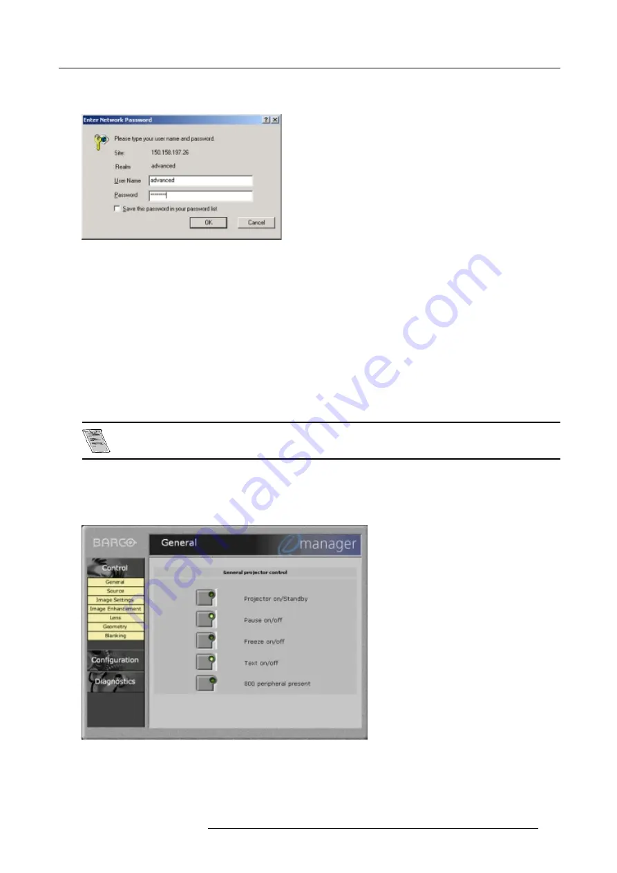
When selecting an item in the control drop down menu, the security login and password will be asked.

Image B-5
Network login window

Factory fitted user name and password are twice ’advanced’. The system administrator can change the user name and password
(see Security, page 119).

Once your password is correctly entered, all items in the control menu are available.

B.4.2

General Control

What can be done

The following items can be switched on or off:

projector on/off (off is equal to standby)

pause on/off

freeze on/off

test on/off

The 800 peripheral present item is not selectable, but if such a peripheral is present the green light lights up.

How to select

1. Click on one of the buttons on the content pane. (image B-6)

The indicated function can be switched on or off. When the green light in the button lights up, the function is on.

Image B-6
Control General window

R5976483 BARCOSLM R6 17092002

113

Содержание BARCOSLM R6

Страница 1: ...BARCOPROJECTION BARCOSLM R6 R9001901 OWNERS MANUAL 17092002 R5976483 01 ...

Страница 2: ...Barco nv Events Noordlaan 5 B 8520 Kuurne Phone 32 56 36 89 70 Fax 32 56 36 88 24 E mail events barco com Visit us at the web www barco com Printed in Belgium ...

Страница 3: ...dically made to the information in this publication these changes are incorporated in new editions of this publication Copyright All rights reserved No part of this document may be copied reproduced or translated It shall not otherwise be recorded transmitted or stored in a retrieval system without the prior written consent of BARCO Trademarks Brand and product names mentioned in this manual may b...

Страница 4: ......

Страница 5: ...t slot 1 2 28 4 5 5 Serial Digital Input slot 3 4 30 4 5 6 HD SDI Digital input slot 3 4 31 4 5 7 Digital Video Decoder Input 32 4 6 Communication Connections 33 4 6 1 RS232 RS422 Connection 34 4 6 2 Communication with peripherals 34 4 6 3 Network connection 34 5 Getting Started 37 5 1 RCU Local keypad 37 5 2 Terminology overview 37 5 3 Operating the projector 38 5 3 1 Switching on 38 5 3 2 Switch...

Страница 6: ...Picture in Picture PiP 75 7 6 1 Introduction to PiP 75 7 6 2 Picture in Picture activation 76 7 6 3 Picture in Picture source 76 7 6 4 Position of Picture in Picture window 76 7 6 5 Set up of the Quick Selection 77 8 Installation Mode 79 8 1 Start up of the Installation mode 79 8 2 Input Slots 79 8 3 800 peripheral 80 8 3 1 Defining the output module of the RCVDS05 80 8 3 2 Defining the Infrared C...

Страница 7: ...erview 105 B Barco Control Manager 109 B 1 General requirements 109 B 2 About the control manager 109 B 3 Control manager Start Page 110 B 4 Control 111 B 4 1 Start up 111 B 4 2 General Control 113 B 4 3 Source 114 B 4 4 Image Settings 114 B 4 5 Image Enhancement 115 B 4 6 Lens adjustment 115 B 4 7 Geometry adjustment 116 B 4 8 Blanking adjustment 117 B 5 Configuration 118 B 5 1 Start up 118 B 5 2...

Страница 8: ...Table of contents 4 R5976483 BARCOSLM R6 17092002 ...

Страница 9: ... does happen switch off and unplug the mains supply immediately Do not operate the projector again until it has been checked by qualified service personnel The projector must always be mounted in a manner which ensures free flow of air into its air inlets and unimpeded evacuation of the hot air exhausted from its cooling system Heat sensitive materials should not be placed in the path of the exhau...

Страница 10: ...1 Safety Instructions Extra Safety manual Read also safety instructions in separate manual R5976125 6 R5976483 BARCOSLM R6 17092002 ...

Страница 11: ...tation the projector is surrounded with foam The package is secured with banding and fastening clips To unpack 1 Release the fastening clips 2 Remove the banding Handle as shown in the drawing image 2 1 3 Take the projector out of its shipping carton and place it on a table Image 2 1 Save the original shipping carton and packing material they will be necessary if you ever have to ship your project...

Страница 12: ...2 Packaging and Dimensions 2 4 Projector Case Dimensions The dimensions are given in mm 25 4mm 1 inch Image 2 2 Front view dimensions Image 2 3 Side view dimensions 8 R5976483 BARCOSLM R6 17092002 ...

Страница 13: ...2 Packaging and Dimensions Image 2 4 Top view dimensions R5976483 BARCOSLM R6 17092002 9 ...

Страница 14: ...2 Packaging and Dimensions 10 R5976483 BARCOSLM R6 17092002 ...

Страница 15: ...visable and desirable to have this contamination removed prior to it reaching the projectors clean air supply Devices or structures to extract or shield contaminated air well away from the projector are a prerequisite if this is not a feasible solution then measures to relocate the projector to a clean air environment should be considered Only ever use the manufactures recommended cleaning kit whi...

Страница 16: ...l preference and another consideration called the Viewing angle In considering the type of screen to choose determine where the viewers will be located and go for the highest gain screen possible A high gain screen will provide a brighter picture but reduce the viewing angle For more information about screens contact your local screen supplier What image size How big should the image be The projec...

Страница 17: ...ation Guidelines Table mounted front projection second way Image 3 2 Table mounted configuration up side down Ceiling mounted front projection Image 3 3 Ceiling mounted projector R5976483 BARCOSLM R6 17092002 13 ...

Страница 18: ...unted projector 3 3 Safety Area around projector Safety area Make sure the projector is located so that the air inlets and outlets for the cooling system are not obstructed Leave a safety area A of about 1 meter on the left and the right side of the projector 14 R5976483 BARCOSLM R6 17092002 ...

Страница 19: ...lpful while turning screw B menu 3 2 5 Loosen the nut A image 3 7 on the back of the lamp casing nutdriver 10 6 Adjust the screw B image 3 7 with an Allen key by turning a little clockwise until the maximum light output is reached the maxi mum value of the Z AXIS indication on the lamp menu 7 Fasten the nut on the back of the lamp casing to secure this position nutdriver 10 ADJUSTMENT MODE Select ...

Страница 20: ...es Image 3 6 Lamp adjustment access Image 3 7 Never turn the other screws These are factory aligned 3 5 Lenses Overview Lenses Lens selection Lens formulas Lens Installation Cleaning the lens 16 R5976483 BARCOSLM R6 17092002 ...

Страница 21: ...0 24 PDmin 2 03xSW 6 69 PDmax 2 88xSW 9 45 TLD 2 8 5 0 1 PDmin 2 84xSW 0 16 PDmax 5 18xSW 0 38 PDmin 2 84xSW 6 30 PDmax 5 18xSW 14 96 TLD 5 0 8 0 1 PDmin 4 97xSW 0 01 PDmax 8 28xSW 0 29 PDmin 4 97xSW 0 39 PDmax 8 28xSW 11 42 Lens program to calculate the projector distance is available on the BARCO web side http www barco com projection systems customer services lens program asp 3 5 4 Lens Install...

Страница 22: ...ses in a single direction Warning Do not wipe back and forwards across the lens surface as this tends to grind dirt into the coating 3 Do not leave cleaning cloth in either an open room or lab coat pocket as doing so can contaminate the cloth 4 If smears occur when cleaning lenses replace the cloth Smears are the first indication of a dirty cloth Do not use fabric softener when washing the cleanin...

Страница 23: ...h other without using extra tools or accessories How to stack Handle as follow 1 Put the second projector on the first one so that base plate of the second projector matches with the rigging socket of the first projector image 3 12 2 Turn the rigging sockets of the second projector counter clockwise until they are free to move up and down image 3 13 3 Secure the projectors on each other by bringin...

Страница 24: ...stallation Guidelines Image 3 12 Stacking two projectors Image 3 13 Closing the rigging sockets Image 3 14 Mounting the security chain Image 3 15 Mounting the security hook 20 R5976483 BARCOSLM R6 17092002 ...

Страница 25: ... a secured rigging point 1 Push the ring A of the first projector downwards and hold it in that position image 3 17 2 Turn the locked part B of the second projector a quarter counter clockwise and move it upwards Image 3 17 Opening the rigging sockets R5976483 BARCOSLM R6 17092002 21 ...

Страница 26: ...ojector Image 3 18 Mounting the clamps Image 3 19 Mounting the clamps When mounting the projector to the ceiling or to a rigging system always mount security chains How to mount the clamps To fix the clamps to the U profile follow the next procedure 1 Measure the distance center tube as reference between the two used support bars of a truss 2 Slide the clamps holders 2 per profile on its place in ...

Страница 27: ...le as follow 1 Open the fixation handle image 3 21 2 Hook the clamp around the tube The trigger automatically shuts the clamp 3 Close the fixation handle and secure it by turning the hand screw image 3 22 Image 3 21 Opening the rigging clamp Image 3 22 Closing the rigging clamp R5976483 BARCOSLM R6 17092002 23 ...

Страница 28: ...3 Installation Guidelines 24 R5976483 BARCOSLM R6 17092002 ...

Страница 29: ...re hazard refer replacement to qualified service personnel ask to replace with the same type of fuse T7 AH 250V 4 2 Switching on How to switch on 1 Press the power switch to switch on the projector When 0 is visible the projector is switched off When 1 is visible the projector is switched on The projector starts in standby mode The projector indication lamp is red Starting image projection 1 Press...

Страница 30: ...etime of the lamp for a safe operation is 1000 or 1500 depending on lamp type hours max Do not use it longer Always replace with a same type of lamp Call a BARCO authorized service technician for lamp replacement Using a lamp for more than 1000 or 1500 depending on lamp type hours is dangerous as the lamp could explode Lamp Light Output Indication When starting up and the center lumens measurement...

Страница 31: ...ities Image 4 3 Input facilities Input number Type of input 1 Fixed input 5 cable input or DVI input and DVI output 2 Fixed input 5 cable input or DVI input 3 4 Variable inputs Two digital inputs available SDI input R9840110 HD SDI Digital input R9840450 Digital Video Decoder R9841170 4 5 2 Inputs via RCVDS05 Overview When using a RCVDS05 the input configuration must be as follows slot 1 RGB Compo...

Страница 32: ...dule is seated correctly in the guide grooves 4 Press on both handles of the input module until the module plug seats in the connector of the projector image 4 4 5 Secure the input module by tightening both retaining screws 6 Reconnect the power cord to the wall outlet and switch on the projector Image 4 4 How to select the new installed module The new installed module can be selected with the dig...

Страница 33: ...in 16 Hot Plug Detect Pin 5 TMDS DATA4 Pin 17 TMDS DATA0 Pin 6 DDC Clock Pin 18 TMDS DATA0 Pin 7 DDC Data Pin 19 TMDS DATA0 5 Shield Pin 8 No connect Pin 20 TMDS DATA5 Pin 9 TMDS DATA1 Pin 21 TMDS DATA5 Pin 10 TMDS DATA1 Pin 22 TMDS Clock Shield Pin 11 TMDS DATA1 3 Shield Pin 23 TMDS Clock Pin 12 TMDS DATA3 Pin 24 TMDS Clock How to select input slot 1 or 2 1 Key in 1 or 2 on the RCU or the local k...

Страница 34: ... on Y VIDEO S VIDEO DVI When changing from an analog signal on the 5 cable module to the panellink input the indication led on the front panel of the module will switch from the 5 cable input to the DVI panellink input also For the output on fixed slot 1 DVI input DVI in signal is looped through to the DVI out connector as it is Active image active image signal what ever the input is is available ...

Страница 35: ...ity with HD digital sources This avoids the need for analog video processing anywhere in the video production chain and guarantees the ultimate image quality An active loop through of the HD SDI input signal is provided for monitoring or for double and or triple stacking applications How to connect 1 Connect the output of your HD SDI source to the input BNC of the HD SDI input image 4 6 Note The i...

Страница 36: ...nput What can be connected to this input The following source types can be connected S Video Component Video Composite Video Which signal can be connected to the Digital Video Decoder module Connector name Input signal Pb Y Vid Pr S Video Component Video B Y Ys R Y Composite Video Video S Video S Video How to connect 1 Connect the output of your source to the corresponding inputs on the Digital Vi...

Страница 37: ... select the third or fourth slot menu 4 8 7 Press ENTER to toggle Possible indications on the input slot menu VIDEO VDEO VIDEO S VIDEO VIDEO YUV ADJUSTMENT MODE Select a path from below RANDOM ACCESS INSTALLATION SERVICE Select with or then ENTER EXIT to return Menu 4 6 INSTALLATION INPUT SLOTS 800 PERIPHERAL SOURCE SWITCHING NO SIGNAL CONVERGENCE CONFIGURATION LENS QUICK ACCESS KEYS OSD INTERNAL ...

Страница 38: ...ble to control the projector from another room There is a communication line cable between the IR receiver and the projector or the RCVDS The control information from the RCU can now be sent to the IR Remote Receiver The IR Remote Receiver displays the selected source on a 7 segment display Connecting a Rugged Remote to the projector The Rugged Remote Control allows following functions Remote mode...

Страница 39: ...4 Connections Image 4 8 Always use an ethernet cable with ferrite core to connect the projector to the LAN R5976483 BARCOSLM R6 17092002 35 ...

Страница 40: ...4 Connections 36 R5976483 BARCOSLM R6 17092002 ...

Страница 41: ...er to control the projector remotely This remote control is used for source selection control adaptation and set up It includes automatic storing of picture controls Bright ness Sharpness and settings Other functions of the remote control are switching between stand by and operational mode switching to pause blanked picture full power for immediate restarting direct access to all connected sources...

Страница 42: ...eze the projected image 12 ENTER to start up the adjustment mode or to confirm an adjustment or selection in the adjustment mode 13 EXIT to leave the adjustment mode or to scroll upwards when in the adjustment mode 14 Cursor keys on RCU or and keys cursor keys on the local keypad to make menu selections when in the adjustment mode or to zoom focus when the direct access is active Comparison betwee...

Страница 43: ...start 5 3 3 Switching off How to switch off the projector 1 Press first Standby 2 Let cool down the projector until the fans stop blowing at least 15 min 3 Switch off the projector with the power switch 5 3 4 Temperature error DMD Overview When the temperature of one of the DMD is too low or too high the projector will be switched automatically to standby Before switching to standby the following ...

Страница 44: ...he menu highlight first More and press ENTER to display a second service menu Select then Change Language menu 5 3 5 Press ENTER to display the language selection menu 6 Push the cursor key or to highlight the desired language menu 5 4 Note For the moment only English is available ADJUSTMENT MODE Select a path from below RANDOM ACCESS INSTALLATION SERVICE Select with or then ENTER EXIT to return M...

Страница 45: ... to start up the adjustment mode 2 Push the cursor key or to highlight Installation menu 5 5 3 Press ENTER to select 4 Push the cursor key or to highlight OSD menu 5 6 5 Press ENTER to select The OSD menu will be displayed menu 5 7 6 Push the cursor key or to highlight Highlighted item color 7 Press ENTER to toggle between red green and yellow ADJUSTMENT MODE Select a path from below RANDOM ACCESS...

Страница 46: ... RCU to the reflective screen surface image 5 5 Image 5 5 Hardwired Remote Input 1 Plug one end of the remote cable in the connector on the bottom of the RCU 2 Plug the other end in the connector in the front panel of the projector labelled RC image 5 6 Image 5 6 42 R5976483 BARCOSLM R6 17092002 ...

Страница 47: ...Hardwired CTRL2 image 5 7 Image 5 7 Directly to one of the IR sensors When using the wireless remote control make sure you are within the effective operating distance 30m 100ft in a straight line The remote control unit will not function properly if strong light strikes the sensor window or if there are obstacles between the remote control unit and the projector IR sensor R5976483 BARCOSLM R6 1709...

Страница 48: ...There for each projector has its own address Set up an individual Projector Address The set up of a projector address can be done via the software See Change projector address in chapter Service mode Projector controlling Every projector requires an individual address between 0 and 255 which can be set in the Service mode When the address is set the projector can be controlled now RCU for addresse...

Страница 49: ...tion name of the control e g brightness appears on the screen only if text is ON See example screen The length of the bar scale and the value of the numeric indication indicate the current memorized setting for this source The bar scale changes as the control stick on the RCU is pressed or the or buttons on the local keypad Brightness A correct brightness setting is important for good image reprod...

Страница 50: ... Stand by Key When the Stand by key is pressed the image projection is stopped and the projector goes to stand by This situation is used when a projection stop is planned for a longer period 46 R5976483 BARCOSLM R6 17092002 ...

Страница 51: ...he Adjustment mode The adjustment mode opens menu 6 1 2 The cursor key RCU or or keys local keypad are used to make menu selections and also for adjustments 3 The ENTER and EXIT keys are used to move forward and backward through the menu structure 4 The ADJUST key can be used to terminate the adjustment mode while any path selection menu is displayed ADJUSTMENT MODE Select a path from below RANDOM...

Страница 52: ...rd remark When re entering the Adjustment mode it will be necessary to enter the password again when selecting a password protected item Changing your password To change your password see chapter Service Mode Change Password 6 3 Menus on Local LCD Display Overview When text is off no menus will be displayed on the projection screen But on the local LCD display it is still possible to scroll throug...

Страница 53: ...s Adjustment Mode 7 RANDOM ACCESS ADJUSTMENT MODE Overview Overview Flow Picture Services Picture Tuning Geometry ScenergiX Picture in Picture PiP 7 1 Overview Flow Overview Image 7 1 R5976483 BARCOSLM R6 17092002 49 ...

Страница 54: ... character S standard file The second and third character is used for a following number file index The file index for custom files 00 to 63 n source number ppppXpppp active pixel rating i i or blank i interlaced file blank not interlaced Table 7 1 7 2 2 Possible file manipulations Connecting a new source Before using a new source a correct file has to be installed The projector s memory contains ...

Страница 55: ...t up Load file To start up the load file handle as follow 1 Push the cursor key or to highlight Load menu 7 5 2 Press ENTER to select The Load menu displays the corresponding files depending on the installed filter menu 7 6 FILE SERVICE LOAD EDIT RENAME COPY DELETE OPTIONS Select with or then ENTER EXIT to return Menu 7 5 LOAD FILE FILTER LIST All Filename Src resolution video525 s01 1 675x240i vi...

Страница 56: ... image is not perfect If the displayed image is not correct after selecting the best fitting file go to the Edit menu select the active file and change the File settings 7 2 5 Edit File 7 2 5 1 Start up How to start up the Edit menu To start up the EDIT menu 1 Push the cursor key or to highlight Edit menu 7 9 2 Press ENTER to select The Edit file adaptation menu will be displayed menu 7 10 3 Selec...

Страница 57: ...utomatically measured and filled in in the menu table These values will be available when starting up the EDIT procedure of an active file Do not adjust these settings on an active file they are used to identify the input source file How to find the correct values for the item in the Edit file menu Horizontal Total Pixels If the value for Horizontal Total Pixels is wrong sampling mistakes small ve...

Страница 58: ...e source numbers Clamp position Clamping determines the black level of the signal The clamp pulse can be related to the leading or the trailing edge of the sync pulse Use the ENTER key to toggle between leading and trailing Clamp delay The time between the leading edge of the clamp pulse and the locked edge of the sync pulse Can be any value between 0 and 255 Change the value by pushing the cursor...

Страница 59: ...In such cases disabling FILM mode processing is the best cure Banner Protect On or Off Only active when film mode detection is in the on position Use the ENTER key to toggle between on or off FILM mode processing normally processes the entire display but this may cause problems on sources where video and FILM content are mixed One very common example is scrolling banners at the bottom of the scree...

Страница 60: ...1 1 675x240i video525 c01 1 675x240i video525 c02 1 675x240i Active file Video525 c50 Select with or ENTER to accept EXIT to return Menu 7 14 RENAME FILE From file name Video525 c01 To file name demo c10 Select with or Reprogram with or or numeric keys ENTER to confirm EXIT to return Menu 7 15 Changing the characters 1 Push the cursor keys or to select the desired character menu 7 16 Or Change tha...

Страница 61: ...ile name demo c10 Select with or Reprogram with or or numeric keys ENTER to confirm EXIT to return Menu 7 18 Changing the characters 1 Push the cursor keys or to select the desired character menu 7 19 Or Change that character by pushing the cursor keys or Numeric characters can be entered directly with numeric keys on the RCU Or Press ENTER to confirm The copy file is entered in the list of files ...

Страница 62: ...T to return Menu 7 22 7 2 9 File Options Start up 1 Push the cursor key or to highlight Options menu 7 23 2 Press ENTER The option selection menu will be displayed menu 7 24 FILE SERVICE LOAD EDIT RENAME COPY DELETE OPTIONS Select with or then ENTER EXIT to return Menu 7 23 FILE OPTIONS FILE SORT NAME FILE LOAD AUTOMATIC Select with or then ENTER EXIT to return Menu 7 24 File Sort 1 Press ENTER to...

Страница 63: ...to highlight Color Temperature menu 7 27 2 Press ENTER to select The color temperature selection menu will be displayed menu 7 28 PICTURE TUNING COLOR TEMPERATURE GAMMA DECODING EBU DYNAMIC COLOR DEPTH NOISE REDUCTION INPUT BALANCE Select with or then ENTER EXIT to return Menu 7 27 COLOR TEMPERATURE PROJECTOR WHITE COMPUTER 9300K VIDEO 6500K FILM 5400K BROADCAST 3200K CUSTOM BALANCE Select with or...

Страница 64: ...CTION INPUT BALANCE Select with or then ENTER EXIT to return Menu 7 29 7 3 4 Decoding What can be done The possibility is offered to decode the NTSC video signals via the default American IRE standard or via the European EBU standard Decoding a NTSC signal using the European EBU standard may result in a greenish tint How to change the decoding setting 1 Push the cursor key or to highlight Decoding...

Страница 65: ...ge the value by pushing the cursor key or until the desired noise level is reached 4 Press EXIT to return the Picture Tuning menu PICTURE TUNING COLOR TEMPERATURE GAMMA DECODING EBU DYNAMIC COLOR DEPTH NOISE REDUCTION INPUT BALANCE Select with or then ENTER EXIT to return Menu 7 32 7 3 7 Input Balance Why adjusting the input balance The input balance is normally correct adjusted in the factory But...

Страница 66: ... 5 Press ENTER to select 6 Adjust the Brightness to a maximum value until there is just no green noise visible in the black areas 7 Adjust with the cursor keys or or or until there is no red or blue noise visible in the black areas PICTURE TUNING COLOR TEMPERATURE GAMMA DECODING EBU DYNAMIC COLOR DEPTH NOISE REDUCTION INPUT BALANCE Select with or then ENTER EXIT to return Menu 7 33 INPUT BALANCE W...

Страница 67: ... adjustment in such a way the blue and red noise are just visible and a small Brightness increase maintain a grey colour PICTURE TUNING COLOR TEMPERATURE GAMMA DECODING EBU DYNAMIC COLOR DEPTH NOISE REDUCTION INPUT BALANCE Select with or then ENTER EXIT to return Menu 7 36 INPUT BALANCE WHITE BALANCE BLACK BALANCE Select with or then ENTER EXIT to return Menu 7 37 Checking the White Balance There ...

Страница 68: ...below RANDOM ACCESS INSTALLATION SERVICE Select with or then ENTER EXIT to return Menu 7 38 GEOMETRY SHIFT SIZE SIDE KEYSTONE BLANKING ASPECT RATIO 4 3 Select with or then ENTER EXIT to return Menu 7 39 7 4 3 Shift What can be done The image can be shifted in a horizontal or vertical direction Image 7 4 Shift adjustment A Shift to the left B Shift to the right C Shift upwards D Shift downwards 64 ...

Страница 69: ...ue is positive the image is shifted to the right when the value is negative the image is shifted to the left GEOMETRY SHIFT SIZE SIDE KEYSTONE BLANKING ASPECT RATIO 4 3 Select with or then ENTER EXIT to return Menu 7 40 7 4 4 Size What can be done The size can be adjusted in a vertical or horizontal way When adjusting the vertical size The upper side of the image is fixed table and ceiling mounted...

Страница 70: ...ide Keystone menu 7 42 2 Press ENTER to select 3 Push the cursor key or to adjust the keystone of the image When the upper part of the image is wider than the lower part of the image push the cursor key The number indication below the bar scale will be negative When the upper part of the image is smaller than the lower part of the image push the cursor key The number indication below the bar scale...

Страница 71: ... blanking menu menu 7 44 3 Push the cursor key or to highlight the desired blanking 4 Press ENTER to start up the chosen blanking 5 Use the cursor keys to adjust the blanking GEOMETRY SHIFT SIZE SIDE KEYSTONE BLANKING ASPECT RATIO 4 3 Select with or then ENTER EXIT to return Menu 7 43 BLANKING TOP BOTTOM LEFT RIGHT Select with or then ENTER EXIT to return Menu 7 44 7 4 7 Aspect Ratio Purpose To fo...

Страница 72: ...tal scenergix ScenergiX overlap zone vertical scenergix ScenergiX size adjustment Adjusting the black level of the images 7 5 1 Order information Order numbers SLM G5 R9840880 SLM R6 R9840890 SLM G8 G10 R9841500 SLM R8 R10 R9841510 7 5 2 Introduction When available ScenergiX is only available as an option some menu items will be grayed out when this option is not installed Why ScenergiX When worki...

Страница 73: ...that the light output in that zone equals the light output of the rest of the image Image 7 9 ScenergiX Basic Principle 7 5 3 Preparations ScenergiX Preparations To ensure proper ScenergiX adjustment be sure that the following adjustments are done perfectly on all projectors Convergence Electronic Convergence Geometry Color Matching Color Temperature Input Balance Gamma R5976483 BARCOSLM R6 170920...

Страница 74: ...n ENTER EXIT to return Menu 7 47 7 5 5 ScenergiX overlap zone horizontal scenergix Definitions Image 7 10 Scenergix set up Overlap number of pixels that overlap Horizontal resolution of 1 projector 1024 for Graphics versions 1280 for Reality versions Total horizontal screen resolution horizontal resolution of 1 projector x 2 minus overlap Horizontal Resolution source number of active pixels of the...

Страница 75: ... vertical Overlap number of pixels that overlap Vertical resolution of 1 projector 768 for Graphics versions 1024 for Reality versions Total vertical screen resolution Vertical resolution of 1 projector x 2 minus overlap Vertical Resolution source number of active lines of the source Adjustment of Active lines Lact of the first projector 1 Go to File Edit menu of first projector 2 Enter value for ...

Страница 76: ...t the size Only accessible when the status is in the ON position 1 Push the cursor key or to highlight one of the four size adjustments Top Bottom Left or Right menu 7 48 2 Press ENTER to select A pattern with the different areas will be displayed image 7 12 3 Use the cursor keys to move the border of the overlap area to the desired position value between 0 and 255 Set first the width of the first...

Страница 77: ...7 Random Access Adjustment Mode Image 7 12 Width selections Image 7 13 Width set up for projector 1 R5976483 BARCOSLM R6 17092002 73 ...

Страница 78: ...ck level of the remaining image excluding the overlap zone How to adjust 1 Push the cursor key or to highlight Level menu 7 49 2 Press ENTER to activate 3 Adjust the black level of area A until the black level of area A B and C are equal image 7 15 SCENERGIX STATUS ON size TOP BOTTOM LEFT RIGHT black level LEVEL Select with or then ENTER EXIT to return Menu 7 49 Image 7 15 Black level adjustment 7...

Страница 79: ...icture and allows to display multiple windows containing each of them an image The windows may be of the video or data type What are the different possibilities within the PiP mode The input section of the SLM projector allows a combinations of different input signals which may be projected in the 2 windows of the PiP screen The PiP window can be placed in one of the four corners of the main windo...

Страница 80: ...en ENTER EXIT to return Menu 7 50 PIP STATUS ON SOURCE 01 POSITION Top Left QUICK SELECT OFF Select with or then ENTER EXIT to return Menu 7 51 7 6 3 Picture in Picture source Which source displayed in PiP 1 Push the cursor key or to highlight Source menu 7 52 2 Press ENTER to select 3 Enter the source number with the remote control Start always with 0 PIP STATUS ON SOURCE 01 POSITION Top Left QUI...

Страница 81: ...n is active the source inside the PiP window can be switched to another source by entering on the RCU or local keypad first 0 followed immediately by the source number E g for source 2 in the PiP window enter 02 on the RCU How to set 1 Push the cursor key or to highlight Quick Select menu 7 54 2 Press ENTER to toggle between OFF and 0 OFF no quick selection allowed 0 quick selection allowed by usi...

Страница 82: ...7 Random Access Adjustment Mode 78 R5976483 BARCOSLM R6 17092002 ...

Страница 83: ...CONVERGENCE CONFIGURATION LENS QUICK ACCESS KEYS OSD INTERNAL PATTERNS Select with or then ENTER EXIT to return Menu 8 2 8 2 Input Slots What can be done The input configuration of the variable inputs is shown in the Input slots menu To view or the change the input configuration 1 Push the cursor key or to highlight Input Slots menu 8 3 2 Press ENTER to select The input slots menu will be displaye...

Страница 84: ...DI high definition digital input Digital Video Decoder VIDEO VIDEO VIDEO S VIDEO VIDEO YUV What if a switcher is connected to the projector If a RCVDS switched on or VS05 is connected to the projector it will be also indicated on the menu by adding 800 peripheral If no 800 peripheral indication is made on the menu there are still two possibilities no RCVDS or VS05 connected or RCVDS is switched of...

Страница 85: ... of communication can be set to PPM RC5 Defining the communication protocol 1 Push the cursor key or to highlight 800 Peripheral menu 8 7 2 Press ENTER to select 3 Push the cursor key or to highlight Infrared menu 8 8 4 Press ENTER to select 5 Press ENTER to toggle between PPM or RC5 INSTALLATION INPUT SLOTS 800 PERIPHERAL SOURCE SWITCHING NO SIGNAL CONVERGENCE CONFIGURATION LENS QUICK ACCESS KEYS...

Страница 86: ...ION INPUT SLOTS 800 PERIPHERAL SOURCE SWITCHING NO SIGNAL CONVERGENCE CONFIGURATION LENS QUICK ACCESS KEYS OSD INTERNAL PATTERNS Select with or then ENTER EXIT to return Menu 8 9 SEAMLESS SOURCE SWITCHING EFFECT NO TRANSITION ENTER to toggle EXIT to return Menu 8 10 Image 8 1 Example of seamless switching with Fade effect When an effect is selected within seamless source switching wait until the e...

Страница 87: ...lect with or then ENTER EXIT to return Menu 8 12 8 5 2 Changing the Shutdown Setting How to change 1 Push the cursor key or to highlight No Signal menu 8 13 2 Press ENTER to select The no signal menu will be displayed menu 8 14 3 Push the cursor key or to highlight Shutdown menu 8 14 4 Press ENTER to toggle between On or Off INSTALLATION INPUT SLOTS 800 PERIPHERAL SOURCE SWITCHING NO SIGNAL CONVER...

Страница 88: ... Convergence What can be done The convergence of the displayed image can be adjusted only by a qualified service technician How to start up 1 Push the cursor key or to highlight Convergence menu 8 17 2 Press ENTER to select The following message will be displayed Convergence is reserved to qualified service personnel menu 8 18 INSTALLATION INPUT SLOTS 800 PERIPHERAL SOURCE SWITCHING NO SIGNAL CONV...

Страница 89: ...nt What can be done All lens adjustments are motorized and can be adjusted with the RCU The following items can be adjusted zoom focus shift Options same zoom focus for all files yes or no How to start up 1 Push the cursor key or to highlight Lens menu 8 20 2 Press ENTER to select The lens menu will be displayed menu 8 21 INSTALLATION INPUT SLOTS 800 PERIPHERAL SOURCE SWITCHING NO SIGNAL CONVERGEN...

Страница 90: ...the image up or down and or to shift the image left or right 4 When finished press EXIT to go to the lens adjustment menu or press ENTER to go to the zoom focus function LENS ADJUSTMENT ZOOM FOCUS SHIFT OPTIONS Select with or then ENTER EXIT to return Menu 8 23 Options The zoom focus and shift can be set the same for all files 1 Push the cursor key or to highlight Options menu 8 24 2 Press ENTER t...

Страница 91: ...CE CONFIGURATION LENS QUICK ACCESS KEYS OSD INTERNAL PATTERNS Select with or then ENTER EXIT to return Menu 8 26 QUICK ACCESS KEYS F1 F2 F3 F4 F5 LENS ADJUSTMENTS CLEAR ALL Select with or then ENTER EXIT to return Menu 8 27 No functions are preprogrammed 8 10 OSD Overview Color Settings Menu Position 8 10 1 Color Settings How to change 1 Push the cursor key or to highlight OSD menu 8 28 2 Press EN...

Страница 92: ...NTER EXIT to return Menu 8 31 8 11 Internal Patterns What can be done with these internal patterns The projector is equipped with different internal patterns which can be used for measurement purposes Available patterns Outline Hatch Color bars Multiburst Checker board Page Char Alpha numeric char How to select an internal patterns 1 Push the cursor key or to highlight Internal Patterns menu 8 32 ...

Страница 93: ... when the password function is active Enter the password to continue All other password protected items are now available if you stay in the adjustment mode 9 3 Identification What can be seen on the identification screen The identification screen shows the general information of the projector The following items will be displayed Type of projector BARCO SLM R6 Software version Network module yes ...

Страница 94: ...nabled when the password strap second switch of S2 on the controller module is installed Consult an authorized Barco service technician to change the strap position About password types 3 different password levels are built in in the projector software The different levels are owner user guest Depending on your password level some password protected items are accessible and others not The owner wh...

Страница 95: ...ad 5 Select the next password or press ENTER to save the changes Press EXIT to return without saving the new passwords SERVICE IDENTIFICATION CHANGE PASSWORD CHANGE LANGUAGE CHANGE PROJ ADDRESS SERIAL COMMUNICATION NETWORK LAMP MORE Select with or then ENTER EXIT to return Menu 9 6 CHANGE PASSWORD Enter new password OWNER 0000 USER 0000 GUEST 0000 ACCESS CONTROL LIST Select with or then ENTER Repr...

Страница 96: ...USER 0000 GUEST 0000 ACCESS CONTROL LIST Select with or then ENTER Reprogram with or or numeric keys ENTER to confirm EXIT to return Menu 9 9 ACCESS CONTROL LIST Menu O U G E Adj mode Y Y Y Y BARCO LOGO Y Change add Y Y O owner U user G Guest E everybody Select with or then ENTER EXIT to return Menu 9 10 Changing an access possibility 1 Push the cursor key or to select an item in the scroll list 2...

Страница 97: ...Change Projector Address How to change that address 1 Push the cursor key or to highlight Change Proj Address menu 9 13 2 Press ENTER The Change Projector Address menu will be displayed and the actual address will be filled in The first digit is highlighted menu 9 14 SERVICE IDENTIFICATION CHANGE PASSWORD CHANGE LANGUAGE CHANGE PROJ ADDRESS SERIAL COMMUNICATION NETWORK LAMP MORE Select with or the...

Страница 98: ...S 001 BAUDRATE 115200 INTERFACE STANDARD RS232 RS422 TERMINATION ON Select with or then ENTER EXIT to return Menu 9 16 9 7 2 Baud rate Setting Set up To change the baud rate handle as follow 1 Push the cursor key or to highlight Baudrate menu 9 17 The actual baud rate will be displayed 2 Press ENTER to toggle between the available baudrates Default 9600 SERIAL COMMUNICATION PROJECTOR ADDRESS 001 B...

Страница 99: ...u 9 18 9 7 4 RS422 Termination Set up The last projector in a line should be RS422 terminated ON position All others in the line should be in the OFF position To change the termination position 1 Push the cursor key or to highlight RS422 Termination menu 9 19 The actual setting will be displayed 2 Press ENTER to toggle between ON and OFF Default ON SERIAL COMMUNICATION PROJECTOR ADDRESS 001 BAUDRA...

Страница 100: ...ets with a maximum value of 255 separated by a bullet 4 Repeat the above steps for the subnet mask and the default gateway 5 Select APPLY and press ENTER to install the entered addresses If a wrong value for an octet is entered the following error message will be displayed to indicate where the error is located Example of message Invalid octet The maximum value is 255 for each octet menu 9 23 NETW...

Страница 101: ...splay the lamp menu 1 Push the cursor key or to highlight Lamp menu 9 24 2 Press ENTER to select The lamp menu will be displayed menu 9 25 SERVICE IDENTIFICATION CHANGE PASSWORD CHANGE LANGUAGE CHANGE PROJ ADDRESS SERIAL COMMUNICATION NETWORK LAMP MORE Select with or then ENTER EXIT to return Menu 9 24 LAMP Constant Light output OFF Mode NORMAL Serial number R101111 Article number R9840xxx Run tim...

Страница 102: ...ENTER EXIT to return Menu 9 27 Available Settings STATUS ON OFF ON BARCO logo will be displayed on the screen OFF NO BARCO logo displayed on the screen BACKGROUND ON OFF ON BARCO logo will be displayed on a black background OFF BARCO logo will be displayed without any background SHIFT By pushing the cursor key or the BARCO logo can be positioned anywhere on the screen HOT KEY TEXT OFF OFF no key o...

Страница 103: ...t with or then ENTER EXIT to return Menu 9 29 INSTALL ADD INS CLO KEY xxxxxxxxxxxxxx ___________________ Hardware OK Software Not activated Select with or Reprogram with or ENTER to confirm EXIT to return Menu 9 30 9 12 Preset Input Balance Changing these settings may seriously affect the performance of the projector Start Up 1 Push the cursor key or to highlight Preset Input Balance menu 9 31 2 P...

Страница 104: ...ssing How to toggle 1 Push the cursor key or to highlight Advanced Processing menu 9 33 2 Press ENTER to select The Advanced Processing menu will be displayed menu 9 34 3 Select Minimum Delay and press ENTER to toggle between ON or OFF SERVICE BARCO LOGO ADD INS PRESET INPUT BALANCE ADVANCED PROCESSING DIAGNOSIS MORE Select with or then ENTER EXIT to return Menu 9 33 ADVANCED PROCESSING MINIMUM DE...

Страница 105: ... 9 14 3 Formatter How to select the overview 1 Push the cursor key or to highlight Formatter menu 9 39 2 Press ENTER to select An overview of the working of the formatter will be displayed menu 9 40 DIAGNOSIS I2C FORMATTER SMPS Select with or then ENTER EXIT to return Menu 9 39 FORMATTER I2C 34H OK CONFIGURATION OK INITIALISATION OK SELF TEST OK RED DISPLAY OK GREEN DISPLAY OK BLUE DISPLAY OK EXIT...

Страница 106: ...9 Service Mode 102 R5976483 BARCOSLM R6 17092002 ...

Страница 107: ...ion key be programmed A function key can only be programmed when in the adjustment mode Handle as follow 1 Scroll through the menus until the desired menu is reached 2 Press the desired function key for this menu during a few seconds A confirmation menu will be displayed F1 will be used to quickly access this menu menu 10 1 CONFIRM QUICK ACCESS F1 will be used to quickly access this menu ENTER to ...

Страница 108: ...10 Programmable Function Keys 104 R5976483 BARCOSLM R6 17092002 ...

Страница 109: ... 1690 1280 1069 1024 EWS_75 1280x1024 75 025 79 976 135 000 1688 1280 1066 1024 FMR 640x400i 42 323 36 440 28 570 784 640 431 400 FMTO_2 640x400 55 370 24 370 21 056 864 640 440 400 HD_24P 1920x1080 24 000 27 000 74 250 2750 1920 1125 1080 HD_25I 1920x540I 25 000 28 125 74 250 2640 1920 563 540 HD_25P 1920x1080 25 000 28 125 74 250 2640 1920 1125 1080 HD_30I 1920x540I 30 000 33n750 74 250 200 1920...

Страница 110: ...835 47 840 1457 1120 411 375 PC98_3 1120x750 60 000 50 000 78 569 1571 1120 833 750 S1152_66 1152x900 66 004 61 846 94 500 1528 1152 937 900 S1152_76 1152x900 76 637 71 809 108 000 1504 1152 937 900 SDI_625 675x2781 25 000 15 625 13 500 864 720 313 278 SDI_525 675x2401 29 970 15 734 13 500 858 720 263 240 SG_50 1600x1200 50 000 62 500 130 313 2085 1600 1250 1200 SG_60_2 1024x768 60 000 48 780 64 3...

Страница 111: ...20x400 70 087 31 469 28 322 900 720 449 400 VGA75ISO 640x480 75 000 39 375 31 500 800 640 525 480 XGA_60 1024x768 60 000 48 360 64 996 1344 1024 806 768 XGA_70 1024x768 70 000 57 050 78 044 1368 1024 815 768 XGA_70V 1024x768 69 705 56 182 74 610 1328 1024 806 768 XGA_72 1024x768 71 955 58 140 80 000 1376 1024 808 768 XGA_75 1024x768 75 781 61 080 86 000 1408 1024 806 768 XGA75_GS 1024x768 74 534 5...

Страница 112: ...A Standard Source set up Files 108 R5976483 BARCOSLM R6 17092002 ...

Страница 113: ...g the above requirements it should be possible to run the application using an Applet Viewer With most web browsers it is not the web browser itself that executes the Java applet but the Java Virtual Machine VM E g for Microsoft Explorer the latest Java VM can be found at the following URL http www mi crosoft com java vm dl_vm40 htm Required embedded projector software SLM G5 projectors Version 1 ...

Страница 114: ...ctor Below the loca tion of the projector default indicated as Location This name and location can be replaced by any other name or location see Configuration window Settings B 3 Control manager Start Page Starting up 1 Click on Enter to start up the Barco Control Manager The Control Manager start page will be displayed image B 2 Image B 2 About screen 110 R5976483 BARCOSLM R6 17092002 ...

Страница 115: ...f out boxes or slide bars for the active window To select an item click on it in the menu bar and select the desired item in the drop down menu B 4 Control Overview Start up General Control Source Image Settings Image Enhancement Lens adjustment Geometry adjustment Blanking adjustment B 4 1 Start up Start up To start up the control window 1 Click on Control A drop down menu will be displayed image...

Страница 116: ...off Source selecting the desired source Image settings Contrast Brightness Color Tint Sharpness Phase Gamma Image enhancement Noise reduction Dynamic Color Dept CTI on off Decoding ebu or ire Lens Zoom Focus Shift Geometry Image Shift Size Aspect Ratio Keystone Correction Blanking Changing the blanking settings 112 R5976483 BARCOSLM R6 17092002 ...

Страница 117: ...he control menu are available B 4 2 General Control What can be done The following items can be switched on or off projector on off off is equal to standby pause on off freeze on off test on off The 800 peripheral present item is not selectable but if such a peripheral is present the green light lights up How to select 1 Click on one of the buttons on the content pane image B 6 The indicated funct...

Страница 118: ... source Image B 7 Source switching B 4 4 Image Settings How to change The image settings as Contrast Brightness Color Tint Sharpness Phase and Gamma can be changed by 1 moving with the mouse the slide bar up or down Or clicking on the up or down arrow on the edges of the slide bar image B 8 A value indication for the setting will be given just below the slide bar of the adjustment Changing a setti...

Страница 119: ... for the setting will be given just below the slide bar of the adjustment Image B 9 Image Enhancement CTI Color transient improvement CTI and decoding toggle 1 Click with the mouse on the on or off button of the CTI or decoding item to switch on or off What is decoding The possibility is offered to decode the NTSC video signals via the default American IRE standard or via the European EBU standard...

Страница 120: ...try adjustment What can be adjusted Shift Size and Keystone can be adjusted Image B 11 Geometry adjustment Shift adjustment 1 Click and drag the yellow screen in the direction you want to shift the image steps of 8 pixels The black screen indicates its initial position The shift values are given in a text box below the shifted image Or Click once with the mouse on the shift screen and use the curs...

Страница 121: ... the left side of the image is fixed and only the right side can be moved to its exact position Therefore 1 Click on the right side of the image and drag it to the left or right until its correct position is obtained steps of 8 pixels Or Click once on the size screen and use the or keys on the keyboard to resize the image steps of 1 pixel Keystone adjustment Keystone adjustment can be changed by 1...

Страница 122: ... menu will be displayed image B 13 Image B 13 Configuration start up Available items Mail set up to configure up to 3 mail addresses for auto feedback on a pre defined time Security set up of access password for the user and changing the administrator password Settings to set up the projector name location and mail server address Date time set up date time and time zone for your projector Source t...

Страница 123: ...ng options are available General Status contains Projector type Serial number Software version Configuration Projector runtime Lamp runtime Job log Lamp Warnings Advanced diagnostics contains I C errors 4 Fill out the timing options Select the desired timing by clicking in the drop down box next to the e mail address box The following options are possible Daily fill out the exact hour in the at ar...

Страница 124: ...andle as follow 1 Enter the old password Only x s will be displayed on the screen while typing in the new password 2 Enter the new password 3 Enter again the new password to confirm 4 Click on apply to activate the new password B 5 4 Data Time IP Internet Protocol The network layer of TCP IP Required for communication with the internet TCP IP Transmission Control Protocol Internet Protocol The nat...

Страница 125: ...rent time on projector will be adapted Or Fill out the time and date text box with the following mask Time hh mm Date dd mm ccyy The NTP server address box will be grayed out 3 When summer time is active in your region and the time setting set up via the network time check Daylight saving time to obtain the correct time setting during the summer 4 Click on Apply to activate The current time on pro...

Страница 126: ...art up screen Projector location set up 1 Click in the location text field 2 Fill out the location 3 Click on apply to add the location to the general start up screen IP address SMPT server set up 1 Click in the SMTP server text field 2 Fill out the IP address for the SMTP server E mail server Lamp Warning message time 1 Click in the Lamp warning text field 2 Fill out the time a lamp warning messa...

Страница 127: ...page Available items General Status Job Log Advanced Diagnostics B 6 2 General Status What is available The general status page gives an overview of the projector status type of projector current source run time lamp life time software version B 6 3 Job Log Overview The job log screen gives an overview of the last 30 logs stored in the projector R5976483 BARCOSLM R6 17092002 123 ...

Страница 128: ... warnings for this projector at the moment To see the possible errors or warnings of an item click on the button to expand an error list on the right side of the advanced diagnostic screen The lights before the items should be green When a warning or error occured one of the lights in the buttons will be red and the error list for that button will be expand on the right side of the advanced diagno...

Страница 129: ...n Noordlaan 5 B 8520 Kuurne Phone 32 56 36 89 70 Fax 32 56 36 88 24 E mail antoon dejaegher barco com Web www barco com From Date Please correct the following points in this documentation R5976483 01 page wrong correct R5976483 BARCOSLM R6 17092002 ...

Отзывы: