5 of 8
Installation & Operating Instructions
BAPI-Stat 4 Sensor, w/Display, Button Setpoint, Fan or System Mode Control
BA/BS4M Temperature Sensor
rev. 01/18/16
25188_ins_BS4M
Optional Technician Adjustments
(The sensor set-up is factory set per your order. Set-up adjustments are not required)
The unit is shipped ready to install per the order and does not requires any special setup or programming. The following
Setup or Program Menu Changes are available if the installer decides to change the factory settings. Pushing the button
(S2) on the lower right side of the termination board allows the user to change the display from Celsius to Fahrenheit and
back again (See Fig. 6).
ENTERING PROGRAM MODE AND MAKING CHANGES:
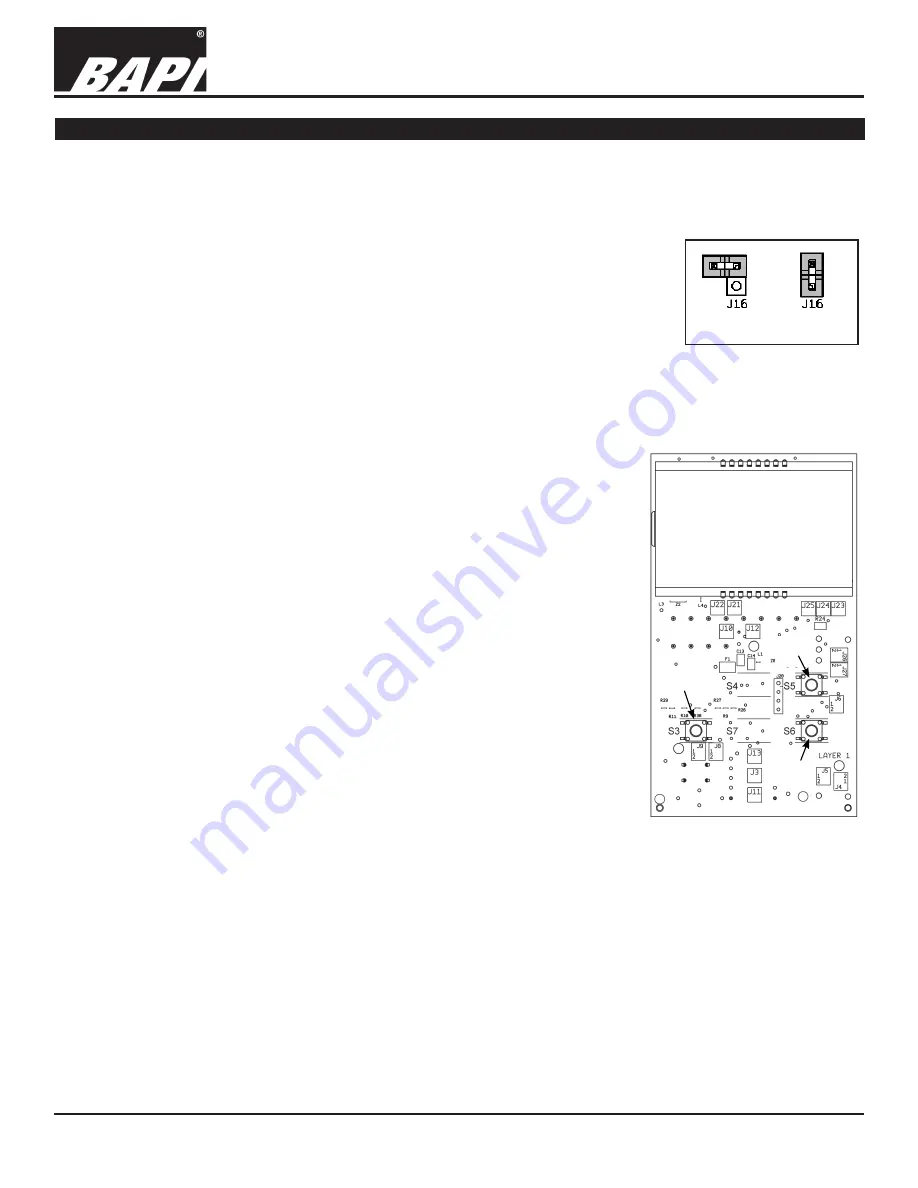
1. Remove cover and install the shunt jumper across the J16 pins (see Fig. 13).
2. Use the Up and Down Setpoint Pushbuttons on the front of the sensor to advance
to the parameter you wish to adjust. (Moves up or down from page to page or from
setting to setting.)
3. Push the Override Pushbutton on the front of the unit to select the menu adjust
parameter. This selects the currently displayed menu.
4. Use the Up and Down pushbuttons to adjust the parameter
5. Push the Override Pushbutton to select the newly adjusted parameter value.
6. You can quit by removing J16 or move to the next parameter using the Up/Down Setpoint buttons.
Note: If your unit does not have the necessary front Up/Down/Override buttons for
adjustment you can remove the board from the housing and use the three
buttons that are on the back of the board. Removing the board requires
removing the centered board mounting screw. The buttons are identified as S3
= Enter (Override), S5 = Up Adjust and S6 = Down Adjust. (See Fig. 14) After
adjustment, place the board back into the cover and insert the center mounting
screw. Do not over tighten.
MODE MENUS:
The setup mode consists of menu pages P1 through P6 for configuring the sensor.
The following adjustments can be done with the program jumper J16 installed.
P1 = Temperature offset:
Adjust Up or Down, -5 to 5° in 0.1° increments
P2 = Setpoint Lockout:
Adjust the value to define the Setpoint mode
0 = Enable Setpoint adjustment (Normal mode)
1 = Disable Setpoint adjustment (No setpoint adjust)
2 = Display Setpoint Only (No room temperature displayed)
3 = No Setpoint Displayed (Rarely used with pushbutton setpoint units)
P3 = Latching Displa
y (see Fig. 15)
-1 = Override Disabled
0 = Momentary Contact, Hollow Man/Solid Man (Typically the normal setting)
1 = Latching Contact: Off/On, No Fan/Fan, Solid Man
2 = Latching Contact: Off/On, No Fan/Fan, No BAPI-Man
3 = Latching Contact: Off/On, Solid Man
4 = Latching Contact: Off/On, No BAPI-Man
5 = Latching Contact: On/Off, Fan/No Fan, Solid Man
6 = Latching Contact: On/Off, Fan/No Fan, No BAPI-Man
7 = Latching Contact: On/Off, Solid Man
8 = Latching Contact: On/Off, No BAPI-Man
9 = Latching Contact: Hollow Man/Solid Man
10 = Non-Latching
See “Latching Override Operation” and “Momentary Override Operation” descriptions for further details.
P4 = Temperature Display:
Adjust value to the display increments desired
0 = Display in whole digits only
1 = Display in 0.5° increments, F or C as chosen on switch S2
2 = Display in 0.1° increments, F or C as chosen on switch S2
P5 = Setpoint Display Low:
Adjust the Low temperature of the desired setpoint range between -9 to 99°.
P6 = Setpoint Display High:
Adjust the High temperature of the desired setpoint range between -9 to 99°.
Fig. 13:
J16 Program
Jumper
Jumper On
Program Mode
Jumper Off
Run Mode
Fig. 14:
Setup Switch
locations on the circuit board
.
Up
Enter
Down


