


7. After checking and adjusting the lighting, run Auto Exposure a second time or adjust the exposure manually by expanding the
Exposure parameters and moving the slider or entering a specific exposure time.
8. Adjust the focus.
a) Place the part so that the area to be focused appears in the center of the Image pane.
b) Expand the Focus Info parameters.
c) Make sure that the Focus Info checkbox is selected.
d) Adjust the focus of the lens while monitoring the focus number.
The focus number is a number between 1 and 255. Use the Image pane to determine when the image is sharp enough, or use the
focus number as a guide. Turn the focus ring on the lens until the focus number is at the highest possible number between 1 and 255.
The focus number is also available on the sensor display.
NOTE: There is no optimal value for this number, but it can be used as a guide if you are setting up more than
one sensor that are focused on the same target.
e) Tighten the locking thumbscrews to secure the lens at the desired focus.
Set Up an Inspection
Vision Manager allows you to set up or make changes to an inspection while the sensor is running. Changes are automatically saved as they
are made.
1.
From the
Sensor screen, click
in the upper right corner to view the inspection list.
2. Click Add New Inspection.
A new inspection is added to the list, the Image pane updates, and the Tools & Results tab shows only the camera tool.
3. Add tools and adjust them as needed for the inspection.
Add a Tool
1.
Click
on the Tools & Results tab.
The Add Tool window opens.
2. Click the desired tool.
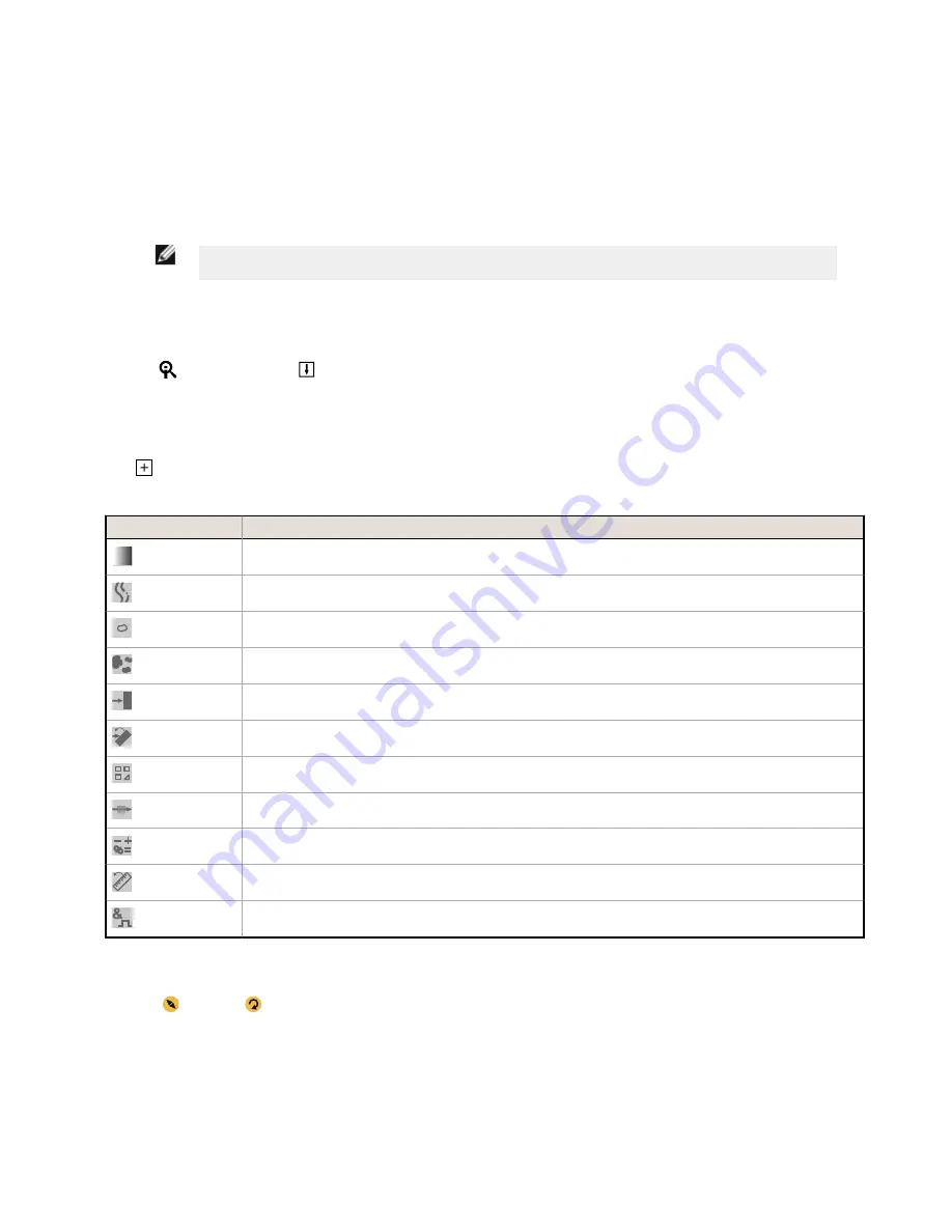
Tool Name
Description
Average Gray
Evaluates pixel brightness within an ROI and computes the average grayscale value.
Bead
Inspects parts for uniformity of adhesive or sealant material, or for uniformity of a gap.
Blemish
Determines whether flaws are present on a part, or detects whether a feature exists on a part.
Blob
Detects and counts/locates groups of connected light or dark pixels within the ROI and designates them as blobs (Binary
Large Objects). After blobs are found, they can be characterized by size and shape.
Edge
Detects and counts transitions between bright and dark pixels (edges). Counts the total number of edges, and determines
the position of each edge.
Locate
Finds the first edge on a part and compensates for translation and rotation of downstream tools (if selected).
Match
Verifies that a pattern, shape, or part in any orientation matches a reference pattern. Can also compensate for translation
and rotation of downstream tools (if selected).
Object
Detects the edges of dark and bright segments and locates their midpoints. Counts dark and bright segments, and
measures the width of each dark and bright segment.
Math
Performs mathematical operations using tool data or user-supplied constants. Includes basic arithmetic, inequality
expressions, and statistical information.
Measure
Measures distance, calculates angles, and creates points and lines for use as inputs to other tools.
Logic
Uses Boolean logic to combine or convert tool results, or to drive discrete outputs from tool results. Logic tool data can be
used to evaluate the results of a single tool or multiple tools.
The tool is added to Tools & Results and the region of interest (ROI) appears on the Image pane.
3. Configure the tool as needed for your application.
a)
Resize
and rotate
the ROI around the feature to be analyzed.
b) Define or view parameters for the tool on the Input tab, such as ROI shape, threshold, or view the histogram.
c) Define pass or fail criteria on the Test tab, such as the count, size, or match.
Save an Inspection to a Computer, Network Drive, or Storage Device
Vision Manager automatically saves inspections to the VE as they are created and modified. Save a copy of the inspection to your computer
or another network location if you want to be able to go back to previous settings.
Use the following procedure to save a copy of an inspection to your computer or a network location.
VE Series Smart Camera
P/N 191667 Rev. C
www.bannerengineering.com - Tel: +1-763-544-3164
7


