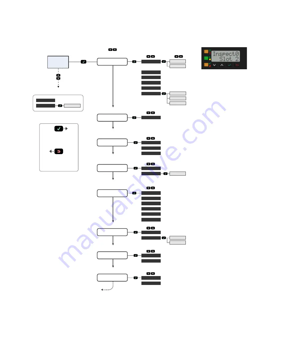
Banner VE200G1A Скачать руководство пользователя страница 10

Sensor Menu

Enter Shortcuts Menu

No

Yes

Yes

100 HD

100 FD

FOCUS#

Home

Screen

ETHER

PCHANGE

IO

VE Series User Interface

Enter

Top Menu

Top Menu

IMAGE

INFO

Sub Menus

or

or

Go Back to Parent Menu

Select Menu Item

Press to Save Setting

Press and Hold to Go Back

to Home Screen

SPEED

LINK

SUBNET

GATEWAY

STATUS

IP

PSELECT

TRIGGER

INPUT

MAC

MAX SPD

By NUM

OUTPUT

FW VER

BOOT

NAME

MODEL

HOUR

SERIAL

SLEEP

VIEW

Ethernet Menu

Product Change by Slot No.

Bit Representation of

Input/Output States

View Current

Focus No.

Sensor Info

(read-only)

DISPLAY

Display Settings

CLEAR

VIEW

SYSERR

System Error

No

Yes

REBOOT

Reboot Device

Return to Top

Yes

FOCUS#

TRIGGER

1000 FD

Figure 11. Menu Map


VE Series Smart Camera

10

www.bannerengineering.com - Tel: +1-763-544-3164

P/N 191667 Rev. C

Содержание VE200G1A

Страница 1: ...on can cause either an energized or de energized sensor output condition CAUTION Electrostatic Discharge Avoid the damage that electrostatic discharge ESD can cause to the Sensor Always use a proven m...

Страница 2: ...asurement and flaw analysis Run time editing allows you to make changes to an inspection while the sensor is running reducing costly downtime Vision Manager also includes a full software emulator allo...

Страница 3: ...cator 1 Connect the Ethernet cable to the sensor 3 and to the computer or Ethernet switch 2 Connect the power discrete I O cable to the sensor 1 and the leads to the appropriate locations See Table 1...

Страница 4: ...the sensor Important Administrative rights are required to install the Vision Manager software 1 Download the latest version of the software from www bannerengineering com 2 Navigate to and open the d...

Страница 5: ...255 255 255 0 2 Open Vision Manager from the desktop or the Start menu The Sensor Neighborhood tab displays and lists the available sensors 3 From Sensor Neighborhood click to connect to the desired...

Страница 6: ...the region of interest ROI for the tool for the selected inspection Figure 9 Sensor Screen Acquire a Good Image The sensor needs to capture a good image of each part to ensure that it correctly passe...

Страница 7: ...oups of connected light or dark pixels within the ROI and designates them as blobs Binary Large Objects After blobs are found they can be characterized by size and shape Edge Detects and counts transi...

Страница 8: ...rete I O settings Figure 10 Discrete I O For more details see the Instruction Manual Sensor Display The LCD display on the top of the sensor provides access to view or change several settings without...

Страница 9: ...menu and return to the parent menu Leave the current menu and return to the Home Screen from any menu Important Pressing Escape discards any unsaved changes In the Sensor Menu a return arrow in the up...

Страница 10: ...INK SUBNET GATEWAY STATUS IP PSELECT TRIGGER INPUT MAC MAX SPD By NUM OUTPUT FW VER BOOT NAME MODEL HOUR SERIAL SLEEP VIEW Ethernet Menu Product Change by Slot No Bit Representation of Input Output St...

Страница 11: ...ices are secure free from bugs viruses interruption errors theft or destruction If the exclusions for implied warranties do not apply to you any implied warranties are limited to 60 days from the date...

Отзывы: