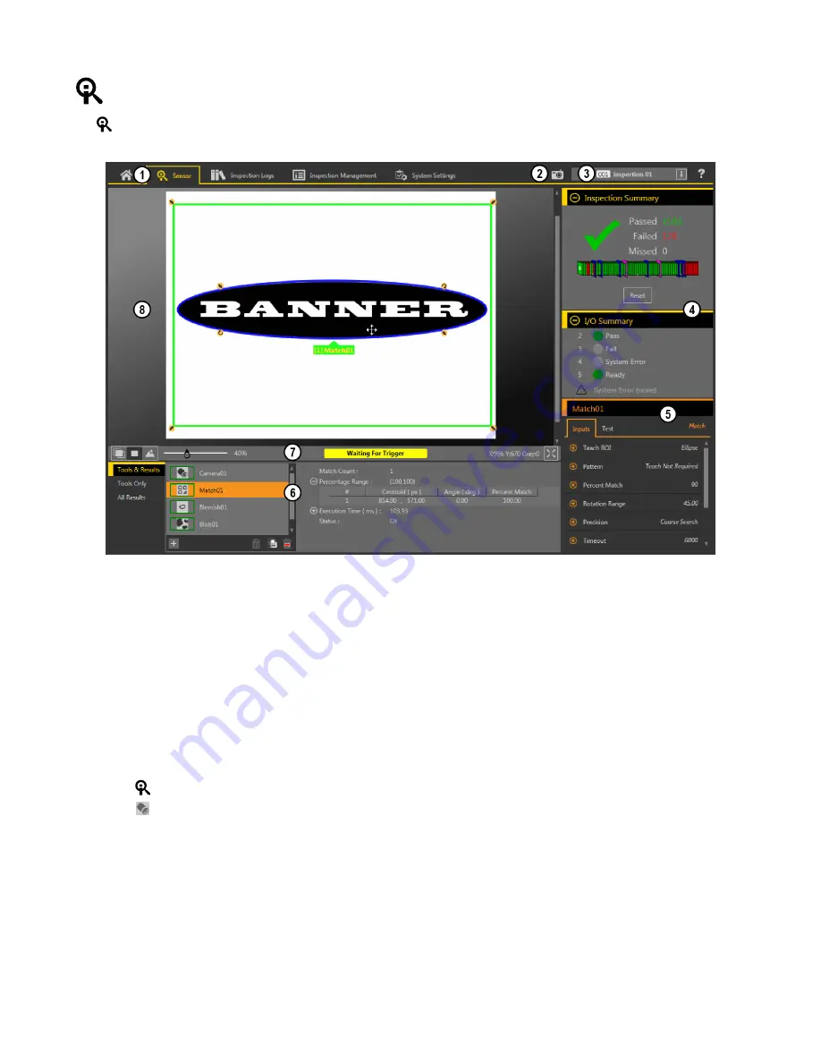
Banner VE200G1A Скачать руководство пользователя страница 6

 Sensor Screen

The 

 Sensor screen displays the information needed to create or modify an inspection.

1. Screens—HomeSensorInspection LogsInspection ManagementSystem Settings
2. Manual Trigger button—Click to manually trigger the sensor
3. Inspection list—Select the desired inspection to start, and to view or modify the inspection
4. Summary pane—Includes the Inspection Summary and the I/O Summary
5. Parameters pane—Includes user-adjustable Inputs parameters or Test parameters for the tools in an inspection, depending on what is selected in the Tools and

Results pane

6. Tools and Results pane—Includes Tools and ResultsTools Only, and All Results, which display the camera tool, the tools that are included in the current

inspection, and the results of the inspection

7. Image Pane Parameters panel—Includes ROI view buttons, zoom, x and y coordinates, grayscale value, and full image display button, as well as sensor

messages

8. Image pane—Displays the current image captured by the sensor; this includes the region of interest (ROI) for the tool for the selected inspection

Figure 9. Sensor Screen

Acquire a Good Image

The sensor needs to capture a good image of each part to ensure that it correctly passes good parts and fails bad parts.
1. Make sure that the lighting is appropriate for your target. Use supplementary lighting, such as a ring light, if necessary.
2.

Click the 

 Sensor screen.

3.

Click the 

camera tool on Tools and Results.

The Inputs parameters display.

4. Set the trigger.

a) Expand the Trigger parameters.
b) In the Trigger Mode list, click Internal (continuous images).

5. Run Auto Exposure.

a) Expand the Imager parameters.
b) Expand the Auto Exposure parameters, and click Start to run.

6. Check the lighting on the part.

• Make sure that the lighting is constant and consistent (unchanging over time, no shadows or hot spots).
• Capture the shape and form of the target object with lighting that optimizes its contrast and separates the feature of interest from the

background. Depending on the target, consider other Banner lights.

• Adjust the mounting angle to provide the clearest image of the part features you are inspecting.


VE Series Smart Camera

6

www.bannerengineering.com - Tel: +1-763-544-3164

P/N 191667 Rev. C

Содержание VE200G1A

Страница 1: ...on can cause either an energized or de energized sensor output condition CAUTION Electrostatic Discharge Avoid the damage that electrostatic discharge ESD can cause to the Sensor Always use a proven m...

Страница 2: ...asurement and flaw analysis Run time editing allows you to make changes to an inspection while the sensor is running reducing costly downtime Vision Manager also includes a full software emulator allo...

Страница 3: ...cator 1 Connect the Ethernet cable to the sensor 3 and to the computer or Ethernet switch 2 Connect the power discrete I O cable to the sensor 1 and the leads to the appropriate locations See Table 1...

Страница 4: ...the sensor Important Administrative rights are required to install the Vision Manager software 1 Download the latest version of the software from www bannerengineering com 2 Navigate to and open the d...

Страница 5: ...255 255 255 0 2 Open Vision Manager from the desktop or the Start menu The Sensor Neighborhood tab displays and lists the available sensors 3 From Sensor Neighborhood click to connect to the desired...

Страница 6: ...the region of interest ROI for the tool for the selected inspection Figure 9 Sensor Screen Acquire a Good Image The sensor needs to capture a good image of each part to ensure that it correctly passe...

Страница 7: ...oups of connected light or dark pixels within the ROI and designates them as blobs Binary Large Objects After blobs are found they can be characterized by size and shape Edge Detects and counts transi...

Страница 8: ...rete I O settings Figure 10 Discrete I O For more details see the Instruction Manual Sensor Display The LCD display on the top of the sensor provides access to view or change several settings without...

Страница 9: ...menu and return to the parent menu Leave the current menu and return to the Home Screen from any menu Important Pressing Escape discards any unsaved changes In the Sensor Menu a return arrow in the up...

Страница 10: ...INK SUBNET GATEWAY STATUS IP PSELECT TRIGGER INPUT MAC MAX SPD By NUM OUTPUT FW VER BOOT NAME MODEL HOUR SERIAL SLEEP VIEW Ethernet Menu Product Change by Slot No Bit Representation of Input Output St...

Страница 11: ...ices are secure free from bugs viruses interruption errors theft or destruction If the exclusions for implied warranties do not apply to you any implied warranties are limited to 60 days from the date...

Отзывы: