


5.7 Applying Power to the B2 or S2 Models
Apply power using either 12 to 30 V DC or a 12 V DC solar panel and 12 V sealed lead acid battery.
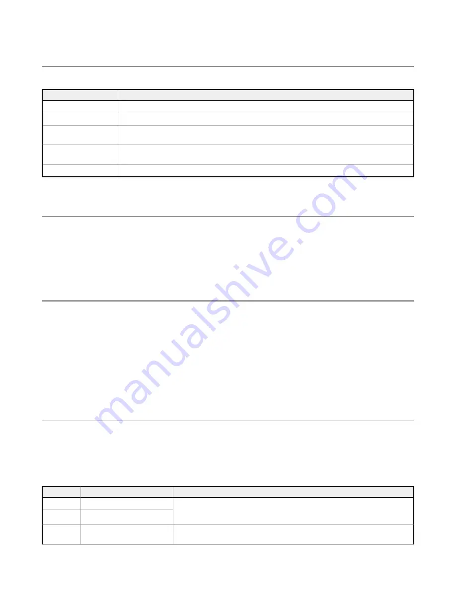
Table 15: Power pins for the B2 and S2 models
Pin
Description
Pin 1
No connection
Pin 2
12 to 30 V DC input (+) or solar panel connection (+)
Pins 3, 5, 8, 13, 18, 31, 34,
36, 41, 44, and 48
Main logic ground for the DXM
Pin 4
Solar or backup battery positive input. Battery voltage must be less than 15 V DC. Use only a sealed lead acid (SLA)
battery.
Pin 23, 26, 35, and 45
Courtesy power output, configuration based on jumper block E (see
on p. 29)
5.8 Connecting a Battery
When attaching a battery to the DXM as a backup battery or as a solar battery, verify the charging algorithm is set properly.
The factory default setting for the battery charging algorithm assumes you are using 12 to 30 V DC to recharge the battery.
The charging algorithm is designed to work with a sealed lead acid (SLA) battery only.
•
When using 12 to 30 V DC, connect the 12 to 30 V DC + to pin 2 and connect the ground to pin 3.
•
When using main dc power with a back up battery (default configuration), connect the incoming main power pin 2 (+)
and to pin 3 (-). Connect the 12 V sealed lead acid battery to pin 4 (+) and pin 5 (-). The incoming main power must
be 15 to 30 V dc to charge the battery.
5.9 Supplying Power from a Solar Panel
To power the DXM-Bx Wireless Controller from a 12 V dc solar panel, connect the solar panel to power pins 2(+) and 3(-).
Connect a 12 V dc sealed lead acid (SLA) rechargeable battery to pins 4(+) and 5(-).
The factory default setting for the battery charging configuration assumes you are using 12 to 30 V DC power to recharge the
battery. If the incoming power is from a solar panel, you must change the charging configuration.
The battery charging configuration defaults to a battery backup configuration. To change the charging configuration from the
menu system:
1. From the DXM LCD menu, navigate to
System Config
>
I/O Board
>
Charger
.
2. Select
Solar
for solar panel configurations or
DC
for battery backup configurations.
To change the charging configuration by writing to Modbus register 6071 on the I/O base board (Slave ID 200):
1. Write a 0 to select the solar power charging configuration.
5.10 Connecting the Communication Pins
The base board communications connections to the device are RS-485 (primary), RS-485 (secondary) or RS-232.
RS-485
—The primary RS-485 bus is a common bus shared with the radio board (Modbus Slave ID 1). The DXM is defined
as the Modbus Master on this bus. Other internal Modbus slaves include the local processor registers (Modbus Slave ID
199), the base I/O controller (Modbus Slave ID 200), and the display board (Modbus Slave ID 201). When assigning Modbus
Slave IDs to externally connected devices, only use IDs 2 through 198.
RS-232
—The RS-232 bus is not currently defined.
Table 16: Communication pins
Pin
Parameter
Description
Pin 6
Primary RS-485 –
Use this bus to connect to other Modbus Slave devices. The DXM is a Modbus Master device on
this RS-485 port. The Modbus protocol baud rate is user configuration, but is set to 19.2k by
default.
Pin 7
Primary RS-485 +
Pin 9
RS-232 Tx
Serial RS-232 connection. This bus must use a ground connection between devices to operate
correctly.
Sure Cross
®
DXM150 and 1500-Bx Wireless Controllers
30
www.bannerengineering.com - Tel: + 1 888 373 6767