background image

DX80 Quick Start Guide

A setup guide for the DX80 wireless system 

Printed in USA 

09/06 

P/N 128185

Introducing the Banner DX80 Wireless System

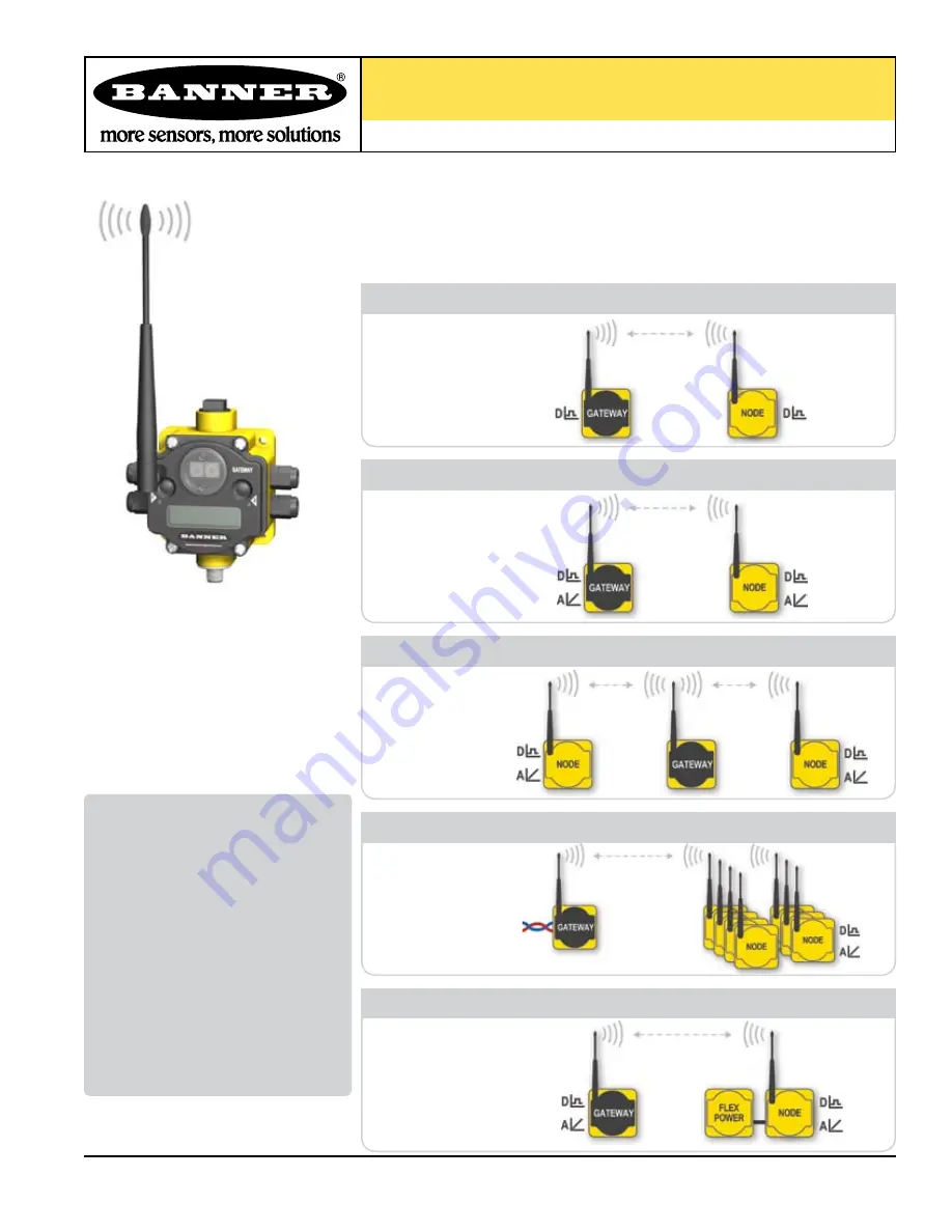
The DX80 wireless system provides continuous monitoring without the burden of wiring or 
conduit installation, and can operate independently or in conjunction with a PLC and/or PC 
software. Configurations of the DX80 wireless system are shown below.

Overview .................................................. 1 
Setting Up ................................................ 2

Quick Start

STEP 1: Set NID & Device Address . 4 
STEP 2: Apply Power  (Gateway)... 5 
STEP 3: Apply power (Node) .........5 
STEP 4: Verify Communications ... 6 
STEP 5: SiteSurvey ...................... 7 

Host Network ........................................... 8 
Product Dimensions ............................... 11 
Menu System ........................................... 12 
Troubleshooting ....................................... 16

Table of Contents

Digital and Analog

Repeater

Host-Connected

FLEX Power

Model Number 

DX80K

*

S6DP

DX80K

*

S6MP

DX80K

*

S3PE

DX80K

*

S3GE

*

All Digital

DX81

Battery Module

Up to 7 Nodes

Model Number


DX80K

*

M6DP1

DX80K

*

M6DP2

DX80K

*

M6DP4

DX80K

*

M6DP7

Model Number


DX80K

*

M6MP1 

DX80K

*

M6MP2

DX80K

*

M6MP7

Model Number


DX80K

*

M3PE1 

DX80K

*

M3GE1 

DX80K

*

S3PE

*

DX80K

*

S3GE

*


DX80K

*

R3PE1 

DX80K

*

R3GE1

Model Number


DX80K

*

R6DP1 

DX80K

*

R6DP2

DX80K

*

R6DP4 

DX80K

*

R6MP1

DX80K

*

R6MP2

Содержание M6DP1

Страница 1: ...SetNID DeviceAddress 4 STEP2 ApplyPower Gateway 5 STEP3 Applypower Node 5 STEP4 VerifyCommunications 6 STEP5 SiteSurvey 7 Host Network 8 Product Dimensions 11 MenuSystem 12 Troubleshooting 16 Table of Contents Digital and Analog Repeater Host Connected FLEX Power Model Number DX80K S6DP DX80K S6MP DX80K S3PE DX80K S3GE All Digital DX81 Battery Module Up to 7 Nodes Model Number DX80K M6DP1 DX80K M6...

Страница 2: ...Button 2 Single click to move down interactive menus Double click to move back to top level menu LED 1 and 2 Provide real time feedback to the user regarding RF link status serial communications activity and Error state LCD Display Six character display provides run mode user information and shows enabled I O point status This display allows the user to conduct a Site Survey RSSI assign Network ID...

Страница 3: ...0 housing is rated IEC IP67 Mounting Hole 10 M5 Clearance Mounting Holes accept metric M5 or UNC UNF 10 hardware DIN rail mount adapter bracket available Wiring Terminal Strip Wiring Terminal Wiring terminal is of spring clip type Each of the 16 wiring terminals will accept wire sizes AWG 12 28 or 2 5 mm2 Port PG 7 Gland or Blank PG 7 threaded port can accept provided cable glands or blanks Ribbon...

Страница 4: ...ithin the same network set the Left Rotary Switch to 1 Assign the same NID to all devices within a single network 0 15 A F is 10 15 respectively On the Gateway set the Right Rotary Switch to 0 A Device Address of 0 on the Gateway will display settings for the Gateway itself To view settings for another device on the network adjust the Right Rotary Switch on the Gateway to the respective Device Add...

Страница 5: ... display shows the current I O status of the Gateway The Gateway starts in RUN mode Displays current Network ID NID Device is Gateway Device Address 0 Indicates the current status of the I O The display will cycle through each I O point of the device then return to RUN repeat Apply power This reading occurs only at initial application of power to the Node The LCD display shows the current I O stat...

Страница 6: ... Gateway the Node s LED 2 flashes Red When communication is established the Node s LED 1 flashes Green LED Status LED 1 LED 2 Green ON Power ON Green FLASHING Red ON System Error RS485 Error Red FLASHING RS485 Fault Yellow FLASHING RS485 Active Gateway LED Status LED 1 LED 2 Green ON Green FLASHING RF Link OK Red ON System Error System Error Red FLASHING No RF Link with Gateway out of sync Node Qu...

Страница 7: ...ack to 0 Gateway Change the device readings back to the Gateway Double click Gateway push button 2 Move back to the top level menu Single click Gateway push button 1 Return to RUN mode Single click Gateway push button 1 Single click Gateway push button 1 Install Gateway rotary switch access cover A site survey determines the quality of the link between a Gateway and a given Node The Gateway is use...

Страница 8: ...at the Gateway has no hard wired inputs or outputs enabled or linked Instead all device I O of the Gateway and each Node can be accessed by a Modbus RTU Master device via serial RS485 In order to accomplish this you may first need to configure several system level communications parameters on the DX80 Gateway in addition to the serial hookups shown below 1 BROWN 2 WHITE 3 BLUE 4 BLACK 5 GREY Brown...

Страница 9: ...2 Single click Gateway push button 1 Options are 9600 19200 38400 default is 19200 Single click Gateway push button 2 Baud rate is saved Single click Gateway push button 1 Moves to the Parity field Single click Gateway push button 2 Single click Gateway push button 1 Options are NONE EVEN ODD default is NONE Single click Gateway push button 2 Parity setting is saved Double click Gateway push butto...

Страница 10: ... be vertically oriented for optimal RF communication In addition consider the height of DX80 position to improve reception levels A wireless network can be hindered by radio interference and obstructions in the path between a receiver and transmitter To achieve the best radio performance installation locations for Gateways and Nodes should be carefully considered Increase Height of DX80 Units ...

Страница 11: ...lis MN U S A www bannerengineering com Tel 763 544 3164 DX80 Quick Start Guide 11 DX80 Gateway Node Dimensions DIMENSIONS 65 0 mm 2 56 TOP VIEW BOTTOM VIEW SIDE VIEW 65 0 mm 2 56 80 3 mm 3 16 59 3 mm 2 33 80 8 mm 3 18 126 7 mm 4 99 121 8 mm 4 79 ...

Страница 12: ...nu When power is applied the DX80 immediately enters RUN state Gateway or Node Run state is the normal operating mode for all devices on the wireless network If the user gets lost navigating the menu system they can double click Push Button 2 twice to return to the top level menu Navigating the menu Top level Sub menu item No characters Value of previous item ...

Страница 13: ...RUN mode Gateway or Node RUN mode is the normal operating mode for all devices on the wireless network If the user gets lost navigating the menu system they can double click Push Button 2 twice to return to the top level menu Navigating the menu Top level Sub menu item No characters Value of previous item Node LCD Timeout Press any button to refresh the display if the Node has entered this energy ...

Страница 14: ... polling method to determine RF link status of each Node on the network If after a prescribed number of sequential polling cycles the Node does not acknowledge a message the Gateway considers the link with the Node to be timed out LCD displays on both the Node and Gateway will show ERROR Following a time out the Node de energizes outputs the Gateway or Repeater Node if applicable sets all outputs ...

Страница 15: ...register Node 1 Register 24 Node 2 Register 40 etc In order for the RF link to be reinstated the Host must send a control message to clear the device error message Any Node output registers will be re populated by the latest Gateway register map RF Link Time out Recovery Host connected Link between Gateway and Node 1 recovered It is the responsibility of the Host to handle Node device error messag...

Страница 16: ...ED packets Marginal Site Survey RSSI results If the distance between devices is greater than about 5 000 meters 3 miles line of sight OR objects such as trees or man made obstructions interfere with the path and the MISSED packet count exceeds 30 per 100 packets the following steps should be considered DX80 units should be raised to a higher elevation either by physically moving the devices or ins...

Страница 17: ...nd can radiate radio frequency energy and if not installed and used in accordance with the instructions may cause harmful interference to radio communications However there is no guarantee that interference will not occur in a particular installation If this equipment does cause harmful interference to radio or television reception which can be determined by turning the equipment off and on the us...

Страница 18: ...t Guide P N 128185 Banner Engineering Corp Minneapolis MN U S A www bannerengineering com Tel 763 544 3164 18 Notes P N 128185 Banner Engineering Corp Minneapolis MN U S A www bannerengineering com Tel 763 544 3164 18 ...

Страница 19: ...er Engineering Corp Minneapolis MN U S A www bannerengineering com Tel 763 544 3164 DX80 Quick Start Guide 19 P N 128185 Banner Engineering Corp Minneapolis MN U S A www bannerengineering com Tel 763 544 3164 Notes 19 ...

Страница 20: ...e defective at the time it is returned to the factory during the warranty period This warranty does not cover damage or liability for the improper application of Banner products This warranty is in lieu of any other warranty either expressed or implied Banner Engineering Corp 9714 Tenth Ave No Minneapolis MN 55441 Phone 763 544 3164 www bannerengineering com Email sensors bannerengineering com ...

Отзывы: