INSTALLATION
MANUAL
MODEL 773 SERIES
REINFORCED CRASH ARM
B&B ARMR: A Division of B&B Roadway and Security Solutions
Page 25 of 38
0773-9001 Rev D
B&B ARMR reserves the right to change any information concerning product or specification without notice or obligation.
3.3.8.1.2.
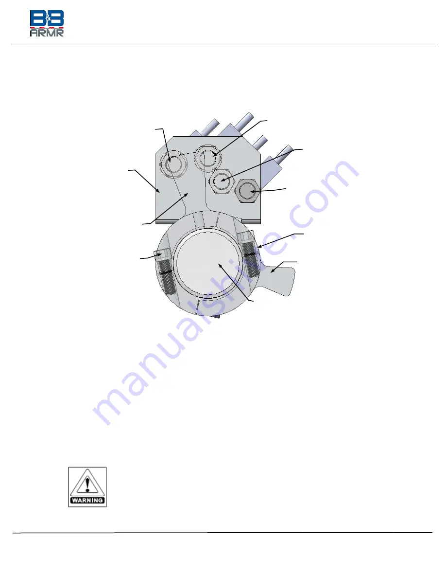
There are four (4) sensors, Up Slowdown, Up Stop, Down Stop and Down
Slowdown. The two flags are sized differently. The larger flag is for
controlling the up position and the smaller flag for the down position.
Figure 17 - Limit Switch Sensor Components
Arm is in the UP Position
(View looking outward from center of barrier)
3.3.8.1.3.
The sensor mounting bracket is connected to the drive stanchion and locks
the sensors in place. The flag collar secures to the hinge pin and allows the
flags to rotate with the hinge pin as the barrier traverses up and down.
3.3.8.1.4.
Adjust the Flag collar to match the position as illustrated in the “FULL
DOWN” position. See
Figure 18 - Sensor UP/DOWN Positioning
Tighten the cap screws.
3.3.8.1.5.
Manually move the barrier arm to the full upright position. IF needed,
adjust the flag collar to match the position as illustrated in the “FULL UP”
diagram. See
Figure 18 - Sensor UP/DOWN Positioning
Tighten the cap screws.
The UP and DOWN flags must be set to within 1/8 in. (3 mm) MAX
distance of the sensors for proper operation. See
Tolerance Diagram (Side View).
Failure to set the limits could result in
damage to the unit upon initial startup. See Section 6 for detailed
installation drawings.
Up Sensor
Flag Collar
Down Stop
Sensor
Up Position Flag
Up Stop
Sensor
Hinge Pin
Down Position Flag
Sensor Bracket
fixed to inside
of Stanchion
Down Slowdown
Sensor
Cap Screws


