background image


INSTALLATION 

MANUAL 

MODEL 773 SERIES 

REINFORCED CRASH ARM 


B&B ARMR: A Division of B&B Roadway and Security Solutions


Page 10 of 38 

0773-9001 Rev D 


B&B ARMR reserves the right to change any information concerning product or specification without notice or obligation. 


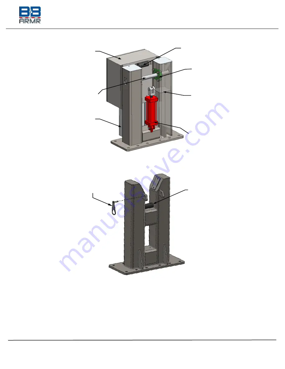
Figure 3 - Drive Stanchion (Model 773HD Shown) 


Figure 4 - Receiver Stanchion

The barrier has an exterior-mounted, dampening strike pad. When the barrier operates at 
the design speed, this damper reduces any whipping action by the arm as it comes to the 
full, raised position. 
 
Both the drive and receiver stanchion are bolted to an anchor assembly cast into a 
subterranean concrete pour (see 

Figure 5 – Subterranean Foundations

). 

Security 

Latching 

Device 

Hinge Pin 

Control/Drive 

Enclosure 

Hydraulic 

Cylinder 

Receiver –  
Arm Strike 
Pad 

Pivot Bearing 

(1x per side) 

Tool Drop 
Plate 

Drive –  
Arm Strike 
Pad 

Marshalling 

Box 

Содержание 773 Series

Страница 1: ...to change any information concerning product or specification without notice or obligation INSTALLATION MANUAL MODEL 773 Reinforced Crash Arm Vehicle Barrier 5900 South Lake Forest Drive Ste 230 McKi...

Страница 2: ...ve System 11 2 4 1 Electric 11 2 4 2 Hydraulic 11 2 4 3 Manual 12 2 5 Options 12 3 INSTALLATION 12 3 1 Introduction 12 3 2 Pre Installation Considerations 13 3 3 Installation Instructions 13 3 3 1 Ste...

Страница 3: ...n concerning product or specification without notice or obligation 5 1 Model 773 Troubleshooting Guide 30 6 APPENDIX 32 6 1 Drawings 32 6 1 1 773E H Series General Layout 32 6 1 2 773E H Series Founda...

Страница 4: ...n Record To assist in documenting the products installed in your system please take a minute to record the following reference information This information can be located on the blue B B ARMR model nu...

Страница 5: ...y other security related products Technical support via telephone and possible on site support with advanced scheduling The equipment covered by this manual is available with a vast variety of options...

Страница 6: ...LIGHTNING FLASH with arrowhead symbol within an equilateral triangle is intended to alert the user to the presence of dangerous voltage within product s enclosure that may be of sufficient magnitude t...

Страница 7: ...on the barrier Ft lbs Foot Pounds A unit of work equal to a force of one pound force through a linear displacement of one foot This is often used to express torque required to secure fasteners such as...

Страница 8: ...Tech Support B B ARMR 5900 South Lake Forest Drive Suite 230 McKinney TX 75070 USA Telephone 800 367 0387 Fax 972 385 9887 E mail info bb armr com E mail2 techsupport bb armr com 2 ORIENTATION 2 1 Ove...

Страница 9: ...terial and transferred to the foundation through the drive and receiver stanchion assemblies Figure 2 Arm Assembly 2 3 Stanchion The drive and receiver stanchions are constructed using heavy gauge ste...

Страница 10: ...nchion The barrier has an exterior mounted dampening strike pad When the barrier operates at the design speed this damper reduces any whipping action by the arm as it comes to the full raised position...

Страница 11: ...electrical components and a programmable logic controller pre programmed with the barrier s operating logic The unit includes a manual operation override so the arm can be raised and lowered during p...

Страница 12: ...t on the options and accessories related to each project 2 5 Options The Model 773 Reinforced Crash Arm Vehicle Barrier is available with the following options Consult your approved submittal package...

Страница 13: ...oil base Consult B B Technical Support if soil compressive strength does not meet this minimum requirement The barrier operates best when installed on a level surface Both drive and receiver stanchion...

Страница 14: ...tanchions 3 3 1 3 Excavate the hole for the Drive and Receiver Stanchion 3 3 1 4 Compact the soil on all sides of each hole 3 3 1 5 To support the concrete foundations of the 773 Barrier and to ensure...

Страница 15: ...color 773 SERIES RECOMMENDED CONDUIT WIRE SIZING DESCRIPTION WIRES AWG VOLTAGE CURRENT CONDUIT NOTES Primary Power 4 10 Varies 20 A 1 in 25 mm 100 ft 31 m one way Safety Loops 2 14 n a n a in 19 mm by...

Страница 16: ...on without notice or obligation Figure 6 Rebar Cage Representation 3 3 2 2 Retention Placement Place Supplied Retention plates and bolts Figure 7 Retention Plate and Anchor Bolts into rebar cage Align...

Страница 17: ...otrude 2 5 in 64 mm above the upper level of the finished foundation to ensure enough thread is available to secure the stanchions 3 3 2 4 There are two 2 remaining retention plates These plates are m...

Страница 18: ...and perpendicular to the axle and verify it falls directly on the center of the Receiver stanchion anchor plate 3 3 2 9 Verify the distance between the two bolt anchors measures the specified clear o...

Страница 19: ...should extend 1 5 in 38 mm above the stanchion once installed 3 3 4 3 Install the supplied flat washers and 1 8 nuts onto the protruding bolts 3 3 4 4 Torque nuts to 150 FT LBS 203 Nm Figure 9 Drive S...

Страница 20: ...t for more details 3 3 7 Step 7 Arm Installation Arm should be installed in the horizontal closed position 3 3 7 1 Lift barrier arm with crane or hoist and lower into position over drive stanchion 3 3...

Страница 21: ...stanchion bearing bolts 4x per weldment and use the adjustment screws 2x per weldment in the stanchion to adjust the position of both bearings Align the arm such that it does not strike or touch the...

Страница 22: ...RE final tightening This helps to ensure each bearing stays aligned before final tightening of bearing bolts 3 3 7 6 Verify the hinge pin is flush to the stanchions sides Tighten the set screws on the...

Страница 23: ...to change any information concerning product or specification without notice or obligation 3 3 7 9 Connect the hydraulic cylinder model 773HD HR or electric actuator model 773ED ER to the Drive stanc...

Страница 24: ...ng product or specification without notice or obligation 3 3 8 Step 8 Final Assembly 3 3 8 1 Limit Switch Alignment 3 3 8 1 1 The limit switch should be installed within the drive stanchion The switch...

Страница 25: ...and allows the flags to rotate with the hinge pin as the barrier traverses up and down 3 3 8 1 4 Adjust the Flag collar to match the position as illustrated in the FULL DOWN position See Figure 18 Se...

Страница 26: ...ions Page 26 of 38 0773 9001 Rev D B B ARMR reserves the right to change any information concerning product or specification without notice or obligation Figure 18 Sensor UP DOWN Positioning Figure 19...

Страница 27: ...le 3 773 Series Options Suggested Conduit and Wire provides general specifications for conduit and wire gauges found on options Consult the unit wiring diagram approved submittal package order acknowl...

Страница 28: ...linder 773Hx is securely attached to the Drive Stanchion and the gate arm with clevis pins Verify unit has hydraulic fluid 773Hx to recommended level Verify control unit is plugged in and cable is rou...

Страница 29: ...r alignment issues Refer to section 3 for adjustment instructions if necessary 4 1 7 Reverse the operation of the electric or hydraulic drive and move the arm downward until it sits firmly in the clos...

Страница 30: ...ice is needed during the commissioning please contact B B 5 TROUBLESHOOTING 5 1 Model 773 Troubleshooting Guide The tables below provide guidance on identifying and correcting any problems with your M...

Страница 31: ...ot missing or have activated Barrier does not close when commanded 1 Verify power is supplied to the unit 2 Verify safety devices have not activated 3 Cycle circuit breaker or check fuse s 4 Check ele...

Страница 32: ...on 6 APPENDIX 6 1 Drawings 6 1 1 773E H Series General Layout B B ARMR 5900 S LAKE FOREST SUITE 230 MCKINNEY TX 75070 800 367 0387 773 SERIES CRASH BARRIER GENERAL LAYOUT NOTES 1 SEE FOUNDATION DRAWIN...

Страница 33: ...g Details NOTES 1 SEE FOUNDATION DRAWING FOR FOUNDATION DETAILS AND REQUIREMENTS 2 SEE SUGGESTED CONDUIT LAYOUT DRAWING FOR RECOMMENDED CONDUIT LAYOUT 3 NOT ALL OPTIONS SHOWN 4 ANCHOR BOLTS WASHERS NU...

Страница 34: ...specification without notice or obligation 6 1 3 773M Series General Layout NOTES 1 SEE FOUNDATION DRAWING FOR FOUNDATION DETAILS AND REQUIREMENTS 2 NOT ALL OPTIONS SHOWN 3 ANCHOR BOLTS WASHERS NUTS R...

Страница 35: ...Details B B ARMR 5900 S LAKE FOREST SUITE 230 MCKINNEY TX 75070 800 367 0387 773 SERIES CRASH BARRIER GENERAL LAYOUT MANUAL OPERATION NOTES 1 SEE FOUNDATION DRAWING FOR FOUNDATION DETAILS AND REQUIRE...

Страница 36: ...GREGATE SIZE SHALL BE 1 INCH 25 4mm 3 THE FOUNDATION SHALL BE POURED ON UNDISTURBED SOIL UTILIZING THE EARTH AS THE FORM FOR THE BOTTOM AND SIDES FOUNDATION SIZE IS BASED ON MINIMUM ALLOWABLE SOIL BEA...

Страница 37: ...form to American Concrete Institute ACI standards Cement shall be per ASTM C150 Maximum aggregate size is 1 in 25 mm Approximate 3 7 cubic yards 2 8 cubic meters per stanchion REBAR Rebar shall be 4 d...

Страница 38: ...nt failure of any kind caused for any reason including but not limited to unauthorized repairs improper installation installation not performed by B B ARMR authorized personnel incoming supply power i...

Отзывы: